Yaskawa Σ-V Series AC Servo Drives Rotational Motor MECHATROLINK-II User Manual
Page 307

9 Appendix
9.1.2 Parameters
9-28
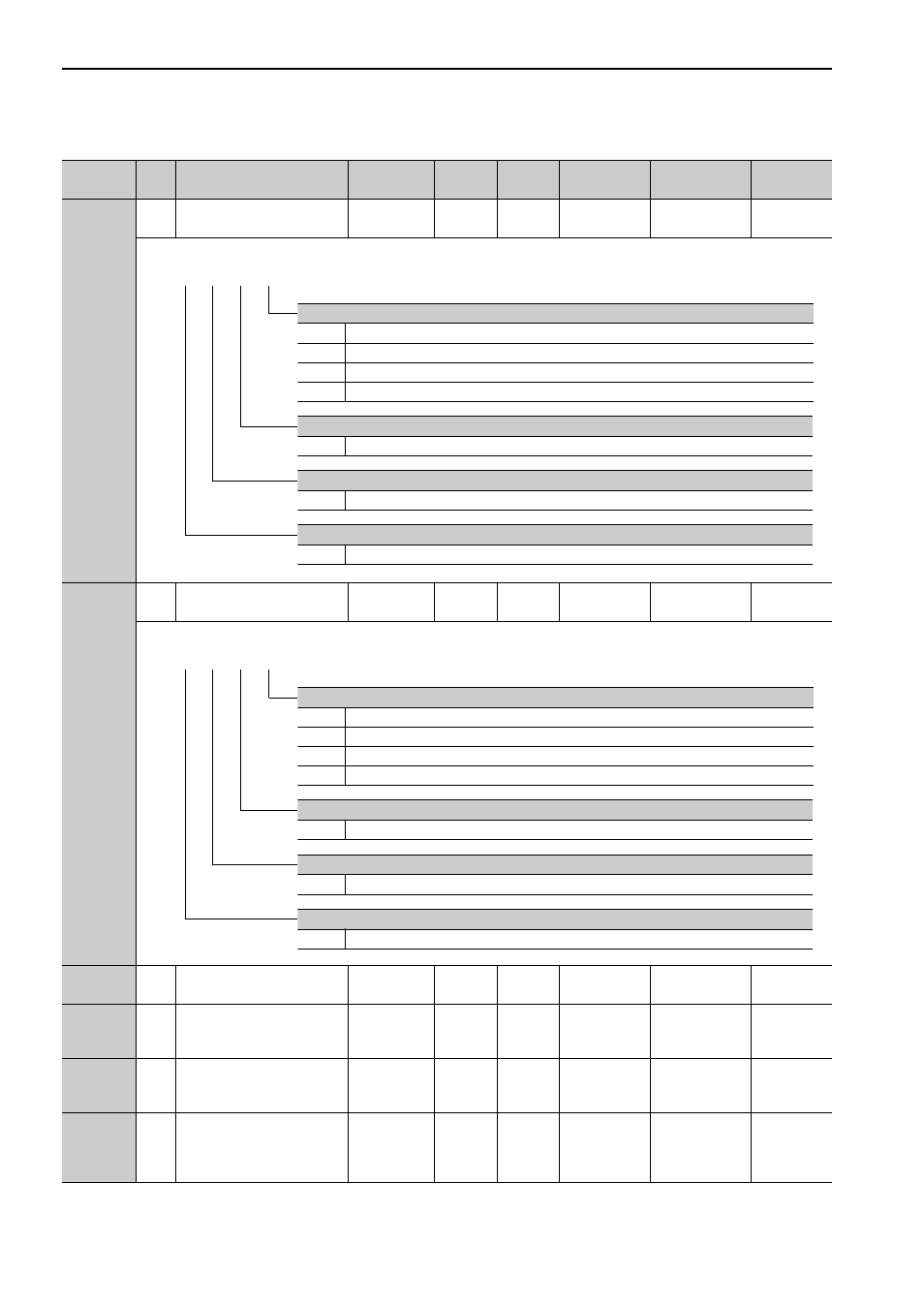
Pn852
2
Latch Sequence Signal 1 to 4
Setting
0000 to 3333
–
0000
Immediately
Setup
*1
Pn853
2
Latch Sequence Signal 5 to 8
Setting
0000
to
3333
–
0000
Immediately
Setup
*1
Pn880
2
Station Address Monitor (for
maintenance, read only)
40 to 5FH
–
0
Immediately
Setup
–
Pn881
2
Setting Transmission Byte
Monitor [byte]
(for maintenance, read only)
17, 32
–
0
Immediately
Setup
–
Pn882
2
Transmission Cycle Setting
Monitor [0.25
μ
s]
(for maintenance, read only)
0 to FFFFH
–
0
Immediately
Setup
–
Pn883
2
Communications Cycle Set-
ting Monitor [x transmission
cycle]
(for maintenance, read only)
0 to 32
–
0
Immediately
Setup
–
∗1.
For details, refer to
Σ
-V Series User’s Manual MECHATROLINK-II Commands
(Manual No.: SIEP S800000 54).
(cont’d)
Parameter
No.
Size
Name
Setting
Range
Units
Factory
Setting
When
Enabled
Classification
Reference
Section
4th 3rd 2nd 1st
digit digit digit digit
n.
Latch sequence 1 signal selection.
0
Phase C
1
EXT1 signal
2
Reserved (Do not change.)
3
Reserved (Do not change.)
Latch sequence 2 signal selection.
0 to 3
Same as latch sequence 1 signal selection.
Latch sequence 3 signal selection.
0 to 3
Same as latch sequence 1 signal selection.
Latch sequence 4 signal selection.
0 to 3
Same as latch sequence 1 signal selection.
4th 3rd 2nd 1st
digit digit digit digit
n.
Latch sequence 5 signal selection.
0
Phase C
1
EXT1 signal
2
Reserved (Do not change.)
3
Reserved (Do not change.)
Latch sequence 6 signal selection.
0 to 3
Same as latch sequence 5 signal selection.
Latch sequence 7 signal selection.
0 to 3
Same as latch sequence 5 signal selection.
Latch sequence 8 signal selection.
0 to 3
Same as latch sequence 5 signal selection.
