ProSoft Technology 5202-DFNT-DFCM4 User Manual
Page 63
DFCM ♦ ProLinx Gateway
Reference
DF1 Master/Slave
Driver Manual
ProSoft Technology, Inc.
Page 63 of 88
October 15, 2010
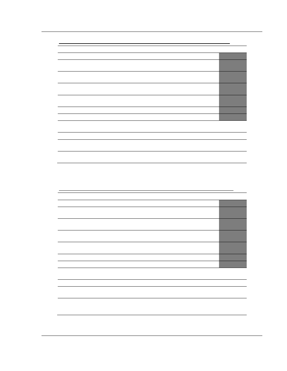
Function Code #501 - Protected Typed Logical Read (Two Address Fields)
Column
Parameter
Description
Parameter
1
Enable/Type Word
0=Disabled and 1=Continuous.
2
Virtual Database Address
This parameter defines the database address of the first
data point to be associated with the command.
3
Poll Interval
Minimum number of seconds to wait before polling with
this command.
4
Count
Number of data word values to be considered by the
function.
5
Swap Type Code
Swap type code for command: 0=None, 1=Swap words,
2=Swap words & bytes and 3=swap bytes in each word.
6
Node Address
Address of unit to reach on the data highway.
7
Function Code = 501
Logical Read Command
8
File Type
SLC file type letter as used in file name string. Valid
values for the system are N, S, F, A, ….
P1
9
File Number
SLC file number to be associated with the command.
P2
10
Element Number
The parameter defines the element in the file where
write operation will start.
P3
11
Not Used
This field is not used by the command. Values entered
in this column will be ignored.
P4
This function reads one or more words of data from a PLC data table.
Function Code #502 - Protected Typed Logical Read (Three Address Fields)
Column
Parameter
Description
Parameter
1
Enable/Type Word
0=Disabled and 1=Continuous.
2
Virtual Database Address
This parameter defines the database address of the first
data point to be associated with the command.
3
Poll Interval
Minimum number of seconds to wait before polling with
this command.
4
Count
Number of data word values to be considered by the
function.
5
Swap Type Code
Swap type code for command: 0=None, 1=Swap words,
2=Swap words & bytes and 3=swap bytes in each word.
6
Node Address
Address of unit to reach on the data highway.
7
Function Code = 502
Logical Read Command
8
File Type
SLC file type letter as used in file name string. Valid
values for the system are N, S, F, A, ….
P1
9
File Number
SLC file number to be associated with the command.
P2
10
Element Number
The parameter defines the element in the file where
write operation will start.
P3
11
Sub-Element Number
This parameter defines the sub-element for the
command. Refer to the AB documentation for a list of
valid sub-element codes.
P4
This function reads one or more words of data from a PLC data table. This
function should work on the following devices: SLC 500, SLC 5/03 and SLC 5/04.