Hardware description, 1 front panel, 1 led indicators – PLANET FNSW-2400PS User Manual
Page 10: 2 rear panel, Ront, Anel
User’s Manual of FNSW-2400PS
2. HARDWARE DESCRIPTION
This product provides two different running speeds – 10Mbps and 100Mbps in the same POE Web Smart Ethernet Switch
and automatically distinguishes the speed of incoming connection.
This section describes the hardware features of FNSW-2400PS. For easier management and control of the
FNSW-2400PS, familiarize yourself with its display indicators, and ports. Front panel illustrations in this chapter display the
unit LED indicators. Before connecting any network device to the FNSW-2400PS, read this chapter carefully.
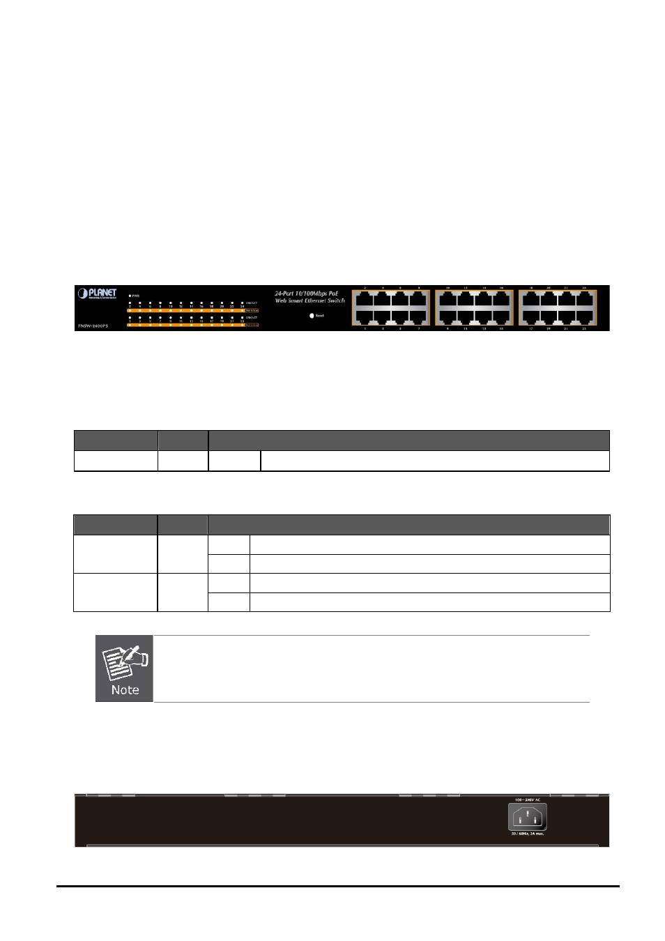
2.1 Front Panel
The Front Panel of the FNSW-2400PS consists of 24x Auto-Sensing 10/100Mbps Ethernet RJ-45 Ports
The LED Indicators are also located on the front panel of the POE Web Smart Ethernet Switch.
Figure 2-1:
FNSW-2400PS Switch Front Panel
2.1.1 LED Indicators
System
LED
Color
Function
PWR
Green
Lights
Indicate that the Switch has power.
Per 10/100Base-TX, PoE interfaces (Port-1 to Por-24)
LED
Color
Function
Lights
: Indicate the link through that port is successfully established.
LNK/ACT
Green
Blink:
Indicate the Switch is actively sending or receiving data over that port.
Lights
: Indicate the port is providing 48VDC in-line power.
PoE In-Use
Orange
OFF:
Indicate the connected device is not a PoE Powered Device (PD).
1. Press the RESET button once. The POE Web Smart Ethernet Switch will reboot automati-
cally.
2.
Press the RESET button for 5 ~ 10 seconds. The POE Web Smart Ethernet Switch will back to
the factory default mode; the entire configuration will be erased.
2.2 Rear Panel
The rear panel of the POE Web Smart Ethernet Switch indicates an AC inlet power socket, which accepts input power from
100 to 240VAC, 50-60Hz, 2A.
Figure 2-2:
FNSW-2400PS Switch rear panel
- 10 -