Figure 3‐3, Redundancy pwr, Offline/ reset – Enterasys Networks Enterasys Platinum Distributed Forwarding Engine 7G4285-49 User Manual
Page 43
Preparing to Install into a Chassis
DFE-Platinum Series Hardware Installation Guide 3-11
4.
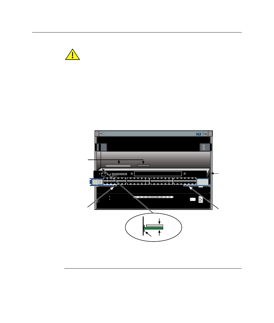
Slide the module into the slot until you can engage the top and bottom locking levers.
5.
Refer to the Caution note above, then rotate the two levers into the closed position.
6.
If the chassis in which the module is installed was powered down for the installation,
turn the power supplies on. Check to see that the module CPU LED settles at solid
green after a few minutes. If the LED does not turn solid green, refer to
for
troubleshooting details.
Figure 3-3 Installing Module into Matrix N3 or N5 Chassis (Matrix N3 shown)
Caution: In step 5, do not force the locking levers to the point that they touch the face of
the front panel. Forcing the locking levers to this point could damage the module and
chassis.
Precaución: En el paso 5, tenga cuidado de no llevar las palancas de cierre a un punto
en donde estén en contacto con el panel frontal. Si lo hace, podría dañar el módulo y/o el
chasis.
1 Card guides
5 Upper locking tab (shown in closed position)
2 Slot 1 (Top slot is slot 3.)
6 Lower locking tab (shown in closed position)
3 Module card
7 FTM2 and power backplane connectors
4 Metal back panel
7C203-1
REDUNDANCY
PWR
100-125V~12.0A
200-240V~6.0A
50/60 Hz
7C203-1
REDUNDANCY
PWR
100-125V~12.0A
200-240V~6.0A
50/60 Hz
1X
G R O U P
1
G R O U P
2
11X
13X
23X
OFFLINE/ RESET
COM
CPU
MGMT
GR
OUP
SELECT
GR
OUP
1
2
3
4
5
6
7
8
9
10
11
12
POE
12
X
14X
24X
G R O U P
3
25X
35X
26X
36X
G R O U P
4
37X
47X
38X
48X
DFE
7G4285-49
Gb ENET
1
2
3
4
Б
Ж
Д
Е
В
Г
А