Liebert hinet, Supported modbus points – Emerson OpenComms-485 User Manual
Page 25
REV. 5
7/6/2007
Liebert Monitoring Group –Development
22
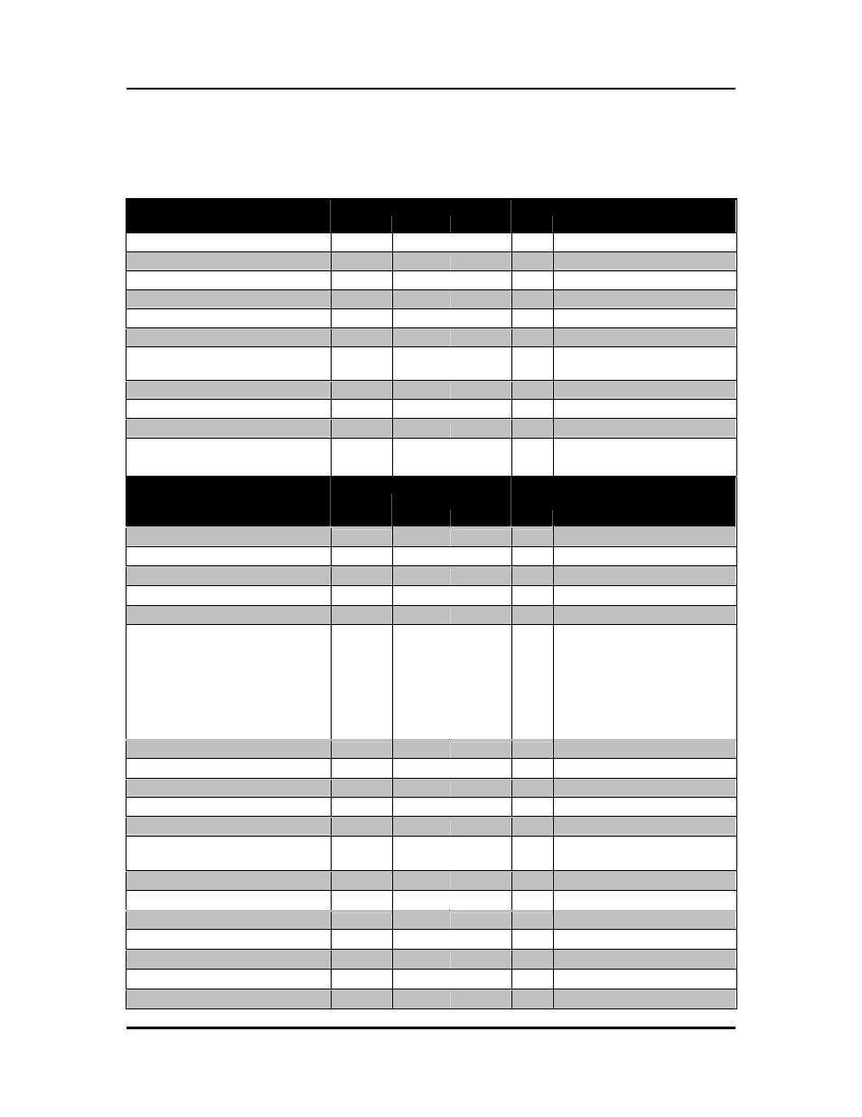
Liebert HiNet
Supported Modbus Points
Data Point
Status
Coil # of Reg. Scale
Notes / Units
DC-To-DC Converter On
10042
1 1
Load On Inverter
10073
1
1
Bypass Active
10074
1 1
Load On Battery
10128
1
1
Permanently On Bypass
10133
1 1
Bypass SCR Open Circuit
10149
1
1
Low Battery - Shutdown
Imminent
10152
1 1
Output Overload
10154
1
1
Inverter Unsynchronized
10160
1 1
Input Power Supply Fail
10186
1
1
Bypass Input
Voltage/Frequency Fault
10202
1 1
Data Point
Input
Register
Holding
Register# of Reg. Scale
Notes / Units
Number Of Input Lines
30004
40004
1
1
Bits 12 - 15
Number Of Bypass Lines
30004 40004
1
1 Bits 4 - 7
Number Of Output Lines
30004
40004
1
1
Bits 8 - 11
Number Of SubModules
30009 40009
1
1
Number Of Battery Cells
30012
40012
1
1
Load Circuit Present
30013 40013
1
There are 16 possible Load
Circuits. So each bit
represents 1 load circuit.
Load Circuit 1 is bit 0, Load
Circuit 2 is bit 1 and so on.
If the bit is 1 then the Load
Circuit is supported.
Load (Apparent Power)
30102
2
1
VA
Load (Real Power)
30104
2 1
W
Input Frequency
30107
1
10 Hz
Output Frequency
30108
1 10
Hz
Battery Voltage
30113
1
1
V
Battery Current
(Charge/Discharge)
30114
1 1
A
Battery Charge Percentage
30116
1
1
%
Ambient Temperature
30119
1 1
deg C
Input Voltage L1
30153
1
1
V
Input Current L1
30154
1 1
A
Output Voltage L1
30163
1
1
V
Output Current L1
30164
1 1
A
Input Voltage L2
30203
1
1
V