Emerson OpenComms-485 User Manual
Page 12
REV. 5
7/6/2007
Liebert Monitoring Group –Development
9
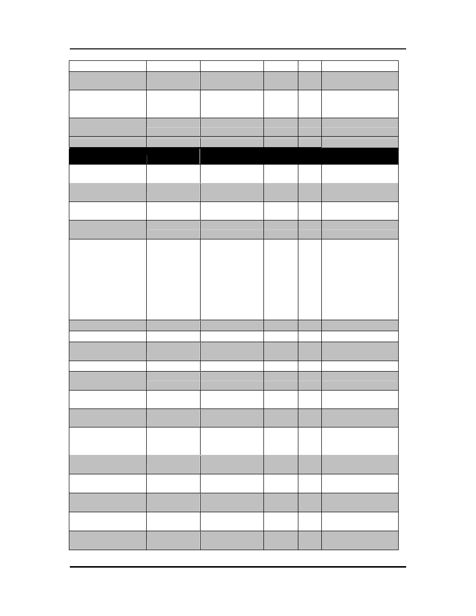
Static Bypass Switch
Inverter
Communication Fail
10281
Rectifier
Communication
Failure
10282
Parallel
Communication Fault
10283
Operation Fault
10289
Data Point
Input Register Holding Register # of Reg. Scale Notes / Units
Number of Input
Lines
30004
40004
1
1
Bits 12 - 15
Number of Bypass
Lines
30004
40004
1
1
Bits 4 - 7
Number of Output
Lines
30004
40004
1
1
Bits 8 - 11
Number Of
SubModules
30009
40009
1
Load Circuit Present
30013
40013
1
There are 16 possible
Load Circuits. So
each bit represents 1
load circuit. Load
Circuit 1 is bit 0, Load
Circuit 2 is bit 1 and
so on. If the bit is 1
then the Load Circuit
is supported.
Module Number
30014
40014
1
Device Module Count
30015
40015
1
Device Redundant
Count
30016
40016
1
Device Module Mode
30017
40017
1
Nominal Power
Rating
30021
40021
2
VA
Nominal Input
Voltage 30027
40027
1
V
Nominal Output
Voltage
30028
40028
1
V
Nominal Static
Bypass Switch
Voltage 30029
40029
1
V
Nominal Input
Frequency
30031
40031
1
10 Hz
Nominal Output
Frequency 30032
40032
1
10
Hz
Nominal Power
Factor
30033
40033
1
100
Nominal DC Bus #1
Voltage 30035
40035
1
V
Nominal DC Bus #2
Voltage
30036
40036
1