3 table 1-2. general specifications (continued) – KEPCO HSP Series Operator Manual User Manual
Page 9
HSPSERIES OPR 050614
1-3
TABLE 1-2. GENERAL SPECIFICATIONS (Continued)
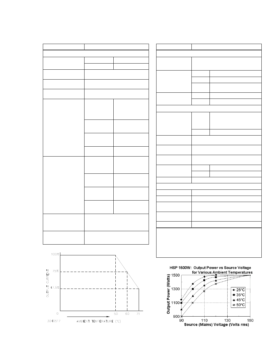
FIGURE 1-2. HSP (ALL), NOMINAL MAINS VOLTAGE:
TEMPERATURE DERATING,
FIGURE 1-3. HSP 1500W, LOW MAINS VOLTAGE:
TEMPERATURE, POWER DERATING
CHARACTERISTIC
REQUIREMENT
SIGNAL AND CONTROL
Remote Error Sensing
3.3V & 5V Models
0.25V per wire
All other Models
0.8V per wire
Remote On/Off Control
Isolated TTL-compatible signal; either logic
high or logic low will disable output.
Load Sharing
Within 5% of load when connected via load
sharing wire (see PAR. 2.7.6).
Load Monitor
0-5V analog signal proportional to output
load current; 5V at 100% of rated load.
Status Flags
(Form C dry relay contacts)
(see PAR. 3.14)
(See Notes 5 and 7.)
POWER
Indicates low source
voltage; signal
asserted a minimum of
5 msec prior to loss of
output voltage.
OUTPUT
Indicates HSP Power
Supply in normal
operating mode.
OVERTEMP
Indicates HSP Power
Supply in overtemper-
ature shutdown.
FAN FAIL
Indicates failure of
internal cooling fan.
Status Indicators
(front Panel LEDs)
(See Note 5.)
POWER
Green; lit when source
voltage is above
minimum limit to
support output voltage.
DCFAIL
Red; lit when output is
outside normal voltage
regulation limits
OVERTEMP
Yellow; lit when over-
temperature protec-
tion is activated.
FAN FAIL
Red; lit when fan
failure latch is
activated.
Front Panel
Test Points
Monitors output voltage and current limit set
points; allows each HSP Power Supply to
be set while operating in any configuration,
including redundant mode.
Front Panel Meter
Accuracy
(M Option only)
Voltmeter: ±1%
Ammeter: ±10% from 25 to 100% of rated
output current.
CHARACTERISTIC
REQUIREMENT
SIGNAL AND CONTROL (CONTINUED)
Auxiliary Voltage
(Isolated)
4.75-5.25V d-c output, 0 - 100mA, parallelable,
output isolated (500 V d-c), Input isolated
(SELV) (See Operating Instructions, PAR. 3.11).
Voltage Set
Programming
Mode selected by
internal switches
(See Note 6.)
(See PAR. 3.3.)
Internal
Multiturn pot
External 1 Resistance: 0-50K
External 2 0-10V, 500
A max
Current Limit
Programming
Internal
Multiturn pot
External
0-10V, 500
A max
ENVIRONMENT
Temperature Range
Operating
0 to 50° C: rated load (50 ° C to 71°
C: derate by 2.5%/° C, Figure 1-2)
For 1500W at lower mains voltage:
see Figure 1-3 and Note 1:
Storage
–40 to +85
o
C
Cooling
Internal d-c fan (inlet, exhaust as indicated in
Figure 1-4).
Humidity
0-95% RH (non-condensing), Operating and
Storage.
Shock
Non-operating, 20g, 11msec 50%, half sine,
3 axes, 3 shocks each axis
Vibration
5-10Hz
10mm, double amplitude
10-55Hz
2g
Altitude
Sea level to 10,000 feet
PHYSICAL
Dimensions
See Figure 1-4.
Weight
16 lbs. (7.3Kg)
Source
Connections
3-pin power entry module (compatible with IEC
320/C19 molded line cord plug.
Load
Connection
Two bus bars (+ and –) 1.0 x 0.125 inch, copper
w/bright nickel finish
Signal Connection
37-pin D-subminiature connector (male)
NOTES 5: Status indicators and status flags are isolated and operate
independently, although driven by the same detector circuit.
6: The POWER/DCFAIL fault detector window tracks pro-
grammed output voltage, however, the overvoltage protection
trip point remains unaffected.
7. Form C contacts: rated from 30V d-c/1A to 60V d-c/0.3A.