2 dcfail indicator and output status flags, Table 3-2. fault detector operation, 3 overtemp indicator and status flags – KEPCO HSP Series Operator Manual User Manual
Page 36: 4 fanfail indicator and status flags, 15 front panel meter (m option) operation, Dcfail indicator and output status flags -10, Overtemp indicator and status flags -10, Fanfail indicator and status flags -10, Front panel meter (m option) operation -10, Fault detector operation -10
3-10
HSPSERIES OPR 050614
3.14.2
DCFAIL INDICATOR AND OUTPUT STATUS FLAGS
The OUTPUT status flags and DCFAIL indicator LED are both controlled by the output fault
detector circuit, which monitors both output voltage and module current to assess d-c output
status. An output fault condition (DCFAIL indicator “ON”) is generated if one of three fault condi-
tions is detected: (1) Overvoltage fault or (2) Undervoltage Fault - output voltage is outside
specified regulation limits, or (3) Undercurrent fault - the power supply module is supplying less
than 70% of the current required by the circuit (as indicated by the load sharing signal) while the
output voltage is within specification limits.
A fault condition is not generated for a combination of overvoltage and undercurrent indications,
as these are mutually exclusive conditions for power supplies which are not part of a parallel-
redundant configuration; this combination does, however, indicate proper operation for opera-
tional power supply modules which are part of a parallel-redundant power scheme in which one
or more power supply modules are presenting overvoltage failures.
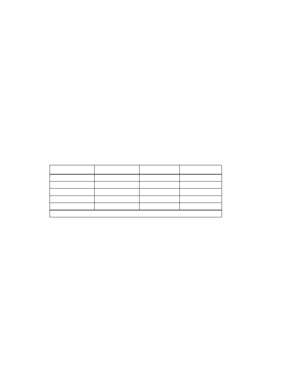
Table 3-2 provides an operating matrix of the DCFAIL status function; see Figure 3-6 for timing
relationships. The output voltage fault limits are ±5% of programmed output voltage, while the
undercurrent fault limit is <70% of required module current; signal reset requires output voltage
recovery to within the specified ±1% regulation range and/or module current recovery to >85%
of required module current, respectively.
3.14.3
OVERTEMP INDICATOR AND STATUS FLAGS
This fault is generated in the event that either the input or output module heatsink temperature
rises above a safe operating level; output regulator shutdown occurs simultaneously. Recovery
occurs automatically upon reduction of internal temperatures to normal levels.
3.14.4
FANFAIL INDICATOR AND STATUS FLAGS
This fault is generated in the event of a failure of the internal cooling fan; a delay of approxi-
mately 5 seconds is incorporated to prevent nuisance indications at turn-on. Reset occurs when
fan operation resumes.
3.15
FRONT PANEL METER (M OPTION) OPERATION
HSP series power supplies are available with a meter option (‘M' suffix) which incorporates a 3½
digit LED meter display on the front panel. The meter provides both voltmeter and ammeter
functions. The V-A rocker switch directly below the meter (Figure 3-7) selects either output volt-
age (V) or module current (A) as the normally-displayed parameter. The associated LED, either
V or A, lights to show the selected switch position. When depressed, the ACTUAL/SETPOINTS
momentary-contact switch located below the V-A selector switch causes the meter to display the
programmed value of output voltage or current limit, as selected by the V-A switch. The opera-
TABLE 3-2. FAULT DETECTOR OPERATION
UNDERVOLTAGE
UNDERCURRENT
OVERVOLTAGE
DCFAIL STATUS
N
N
N
OFF
Y
X
*
ON
N
Y
N
ON
*
N
Y
ON
*
Y
Y
OFF
Y = YES; N = NO; X = DON'T CARE; * = EXCLUDED BY ANOTHER ASSUMED CONDITION