Table 1-2. general specifications, General specifications -2 – KEPCO HSP Series Operator Manual User Manual
Page 8
1-2
HSPSERIES OPR 050614
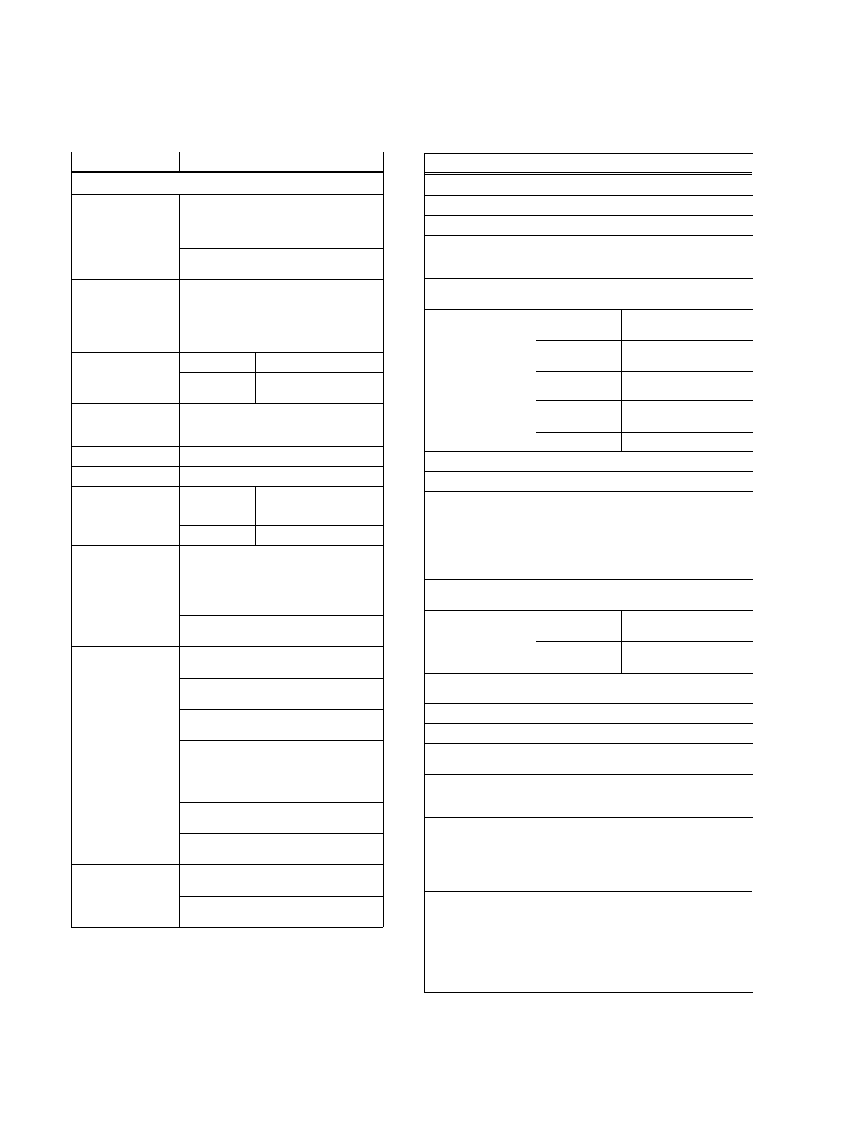
TABLE 1-2. GENERAL SPECIFICATIONS
CHARACTERISTIC
REQUIREMENT
SOURCE INPUT
Source Voltage
AC: Single-Phase,
1000W
1500W
Nominal: 100-250V rms 200-250V rms
Range: 90-277Vrms
180-277V
rms
DC: 125-420V d-c (polarity insensitive)
(See Note 1.)
Brownout Voltage
1000W:75 V a-c typ.
1500W:150 V a-c typ.
Source Frequency
47-440 Hz (Frequencies in excess of 63Hz
will cause leakage current to exceed limits
specified below)
Source Current
120V a-c
11A rms max
240V a-c
1000W: 5.5A rms max
1500W: 8.0A rms max
Power Factor
0.99 typical; 0.96 minimum for all source
conditions and loads from 25% to 100% of
rated load.
Inrush Current
75A Peak max
Efficiency
See Table 1-1.
Withstand Voltage
(See Note 2)
3000V rms
Input to Output
1500V rms
Input to Case
500V d-c
Output to Case
Leakage Current
<0.50mA @ 115V a-c, 47-63Hz
<1.0mA @ 230V a-c, 47-63Hz
Safety
Agency
Approvals
UL Recognized (SELV)
UL 60950 3rd Edition
CSA Certified (SELV)
CSA 22.2 No. 60950-00
Immunity
(See Note 3)
Radiated RF (Ampl. Mod.) (ENV50140)
10V/m, 80-1000MHz
Radiated RF (Pulse Mod.) (ENV50204)
(Pulse) 10V/m, 900MHz
Magnetic Field (EN 61000-4-8)
30A/m, 50Hz
Electrostatic Discharge (EN 61000-4-2)
Contact: 4KV, Air: 8KV
Conducted RF (ENV50141)
10Vrms, 0.15-80MHz
Electrical Fast Transient (EN 61000-4-4)
2KV, Tr/Th = 8/20µs
Input Surge (EN 61000-4-5)
Comm. Mode: 2KV; Diff. Mode: 1KV
Emissions
Conducted RF (CISPR 22)
Class A Limits, 0.15-30MHz
Current Harmonics (EN 61000-3-2)
0-2KHz, any source/load condition)
CHARACTERISTIC
REQUIREMENT
OUTPUT/LOAD
Nominal Voltage
See Table 1-1.
Rated Current
See Table 1-1.
Minimum Output
Current
2% of rated load (lower output conditions may
result in increased output ripple and increased
transient response recovery time).
Output Voltage
Range
See Table 1-1.
Regulation Error
Source Effect
0.1% over full source
voltage range
Load Effect
0.1% from 5% to 100% of
rated load
Temperature
Effect
0.02%/
o
C, 0
o
C o C Time Effect (Drift) 0.1%/24 hr period after 30 Combined Effect 0.3% Ripple and Noise See Table 1-1. Start-up Time 1 sec maximum at rated output current Output Hold-up Time 21.5 msec transparent power loss (no 5 msec following power loss indication >27 msec total time prior to loss of output Turn-on/Turn-off Overshoot Within load transient response envelope Load Transient Response (25% load transient, 2A/µsec rise/fall time) Maximum 3% of nominal output Recovery time 100 sec return to within 1% of set voltage Output Polarity All outputs are floating and can be referenced ±500V d-c. PROTECTION Input Fusing Front Panel circuit breaker (2-line) Low A-C Protection HSP Power supplies will self-protect, no fixed Overvoltage Protection Latched shutdown if output voltage exceeds Overcurrent Protection Constant current limiting (optional undervol- Overtemperature Protection Thermostat shutdown with hysteretic recovery NOTES:1. Safety Agency approval not applicable for noted conditions. 2. 25 o C, 65% RH 3. Per EN 50082-2, Acceptance Criteria A 4. Latched shutdown requires that source power be cycled for restart (optional restart by cycling REMOTE ON/OFF control
min. warm-up
indication)
regulation
excursion
voltage
as required by the user at up to
limit.
user-selected limit (see Operating Instructions,
PAR. 3.8) (see Note 4).
tage-activated latched shutdown (see Operat-
ing Instructions, PAR. 3.9) (see Note 4).
and automatic restart.
signal); see Operating Instructions, PAR. 3.12.