Section 1 - introduction, 1 scope of manual, 2 general description – KEPCO HSP Series Operator Manual User Manual
Page 7: 3 specifications, Table 1-1. model parameters, Scope of manual -1, General description -1, Specifications -1, Model parameters -1, And current limit (i
HSPSERIES OPR 050614
1-1
SECTION 1 - INTRODUCTION
1.1
SCOPE OF MANUAL
This manual contains instructions for the installation and operation of the HSP series of voltage
and current stabilized d-c power supplies manufactured by Kepco, Inc., Flushing, New York,
U.S.A.
1.2
GENERAL DESCRIPTION
The HSP power supply (Figure 1-1) is basically a voltage and current stabilized d-c source with
a relatively sharp crossover between voltage and current mode operation. This permits HSPs to
be used both as conventional regulated voltage sources and in applications such as battery
chargers, where automatic crossover between constant voltage and constant current operation
is required.
HSP power supplies are supplied in a single mechanical size and are nominally rated at either
1000 or 1500 watts of output power. HSP 1000 watt power supplies are designed to operate
over the universal a-c power mains voltage range of 90-277V (47-63Hz), with operation from
125-420V d-c also available. HSP 1500 watt products provide full power over the a-c mains
range of range of 180-277V a-c, and 1000W output power from 90-132V a-c; contact Kepco for
information on operation over other source voltage ranges. Active power factor correction cir-
cuitry limits source current harmonics to negligible levels, significantly improving source power
utilization. Cooling is provided via an internal d-c fan.
The HSP permits adjustment of both output voltage (V
O
) and current limit (I
MAX
), either by inter-
nal (front panel pot) or external (resistance or voltage) methods; programming method is
selected via DIP switches accessed through the top of the unit. Independent circuitry provides
protection against overvoltage, overcurrent and overtemperature failures; fault detection cir-
cuitry monitors performance of the output and critical internal functions, providing both visual
and electrical indicators. A switch-selectable “current walk-in” circuit and optional float/equalize
functions enhance the performance of HSP power supplies for such applications as battery
chargers.
The HSP power supply is specifically designed for both fixed installation operation and, when
used in conjunction with Kepco RA 60 or similar plug-in rack adapters, as a hot replaceable
module in a redundant power system. Forced current sharing and optional internal or external
output blocking diodes enhance power system reliability. Mechanical keying eliminates the risk
of incorrect module insertion. Tool-operated latches on the front panel provide positive security
against casual removal of an operating module.
1.3
SPECIFICATIONS
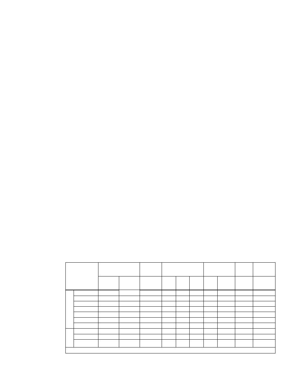
Table 1-1 below indicates specifications for parameters that vary for different HSP models; Table
1-2 lists general specifications that apply to all HSP models.
TABLE 1-1. MODEL PARAMETERS
MODEL
OUTPUT VOLTAGE
(Volts)
OVP
SETTING
(Volts)
OUTPUT CURRENT
(Amps)
RIPPLE
(mV p-p)
NOISE
(mV p-p)
EFFICIENCY
(Percent)
(See Note 1.)
Nominal
(Factory
Set)
Adjustment
Range
Factory
Setpoint
50 ° C
60 ° C
71 ° C
Source
max
Switching
max
(Spike)
20MHz
100% Load
115V a-c
HSP 3.3-230
3.3
0.7-3.6
4.29
230
173
105
20
30
100
71
HSP 5-200
5
1.0-5.5
6.5
200
150
95
20
30
100
72
HSP 12-84
12
2.4-13.2
15.6
84
63
40
20
40
120
73
HSP 15-66
15
3.0-16.5
19.5
66
49.5
31.4
20
40
150
76
HSP 24-42
24
4.8-26.4
31.2
42
31.5
20
20
60
240
77
HSP 28-36
28
5.6-30.8
36.4
36
27
17
20
60
280
78
HSP 48-21
48
9.6-59.2
62.4
21
16
10
20
60
480
80
HSP 24-60
24
4.8-26.4
31.2
60
45
28.6
20
60
120
77
HSP 28-53
28
5.6-30.8
36.4
53
39.8
25.2
20
60
140
78
HSP 48-30
48
9.6-59.2
62.4
30
22.5
14.3
20
60
240
80
1. “R” Model efficiency is typically 2-3% lower.
1
000 W
a
tt
s
150
0 W
a
tt
s
FIGURE 0-1.