10 current walk-in circuit, Figure 3-4. current walk-in characteristic, 11 5vaux floating supply – KEPCO HSP Series Operator Manual User Manual
Page 32: Current walk-in circuit -6, 5vaux floating supply -6, Current walk-in characteristic -6
3-6
HSPSERIES OPR 050614
3.10
CURRENT WALK-IN CIRCUIT
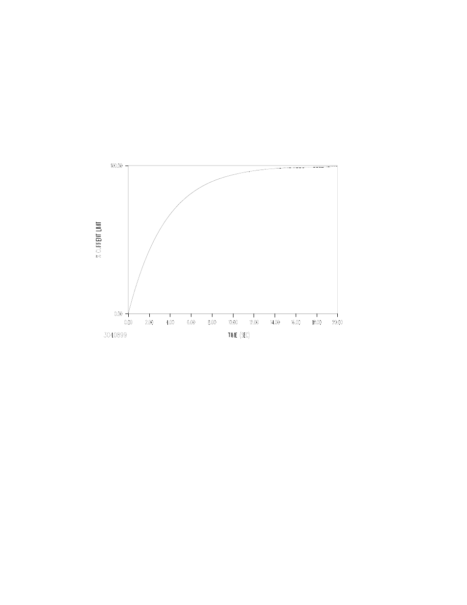
HSP power supplies incorporate a specialized output regulator start-up circuit for applications
involving use of the HSP as a battery charger. This circuit, enabled via switch S1-2, overrides
the normal duty-cycle-based soft-start circuit, which could still result in very fast output current
rise rates into a discharged battery, and substitutes a controlled-current rise circuit with a time
constant in accordance with Bellcore TR-TSY-000947 requirements for telecommunications bat-
tery rectifiers (see Figure 3-4). The circuit is reset each time that the output regulator is shut
down. This circuit is targeted for battery charger applications, but is ideal for any application
which draws very large currents at power-up, such as high-capacitance loads, where this large
current spike could result in circuit disruptions due to inductive coupling.
FIGURE 3-4. CURRENT WALK-IN CHARACTERISTIC
3.11
5VAUX FLOATING SUPPLY
HSP power supplies are equipped with an internal auxiliary supply which provides 5V at loads
up to 100mA. It is derived from the internal cooling fan supply and is, therefore, present when-
ever the source power is within specification and the internal bias supply is operating, regard-
less of the status of the output regulator. This supply is SELV and is isolated from the output
power lines as well, permitting the user to employ this supply to power circuits which do not
share the same ground return as the output; in fact, this supply provides interface power for the
remote inhibit control signals (see PAR. 3.12). Typical applications include single-circuit control
of several HSP power supplies operating at various potentials and polarities with respect to the
controller. The output is protected against overload, and is diode isolated to permit paralleling
with the auxiliary outputs of other HSP units (regardless of model) for additional load capacity or
redundancy. This output is available at I/O connector pins 26 and 25 (5VAUX and AUXRTN,
respectively).