12 remote inhibit/remote reset controls, Figure 3-5. remote inhibit control operation, 13 module current monitor – KEPCO HSP Series Operator Manual User Manual
Page 33: Remote inhibit/remote reset controls -7, Module current monitor -7, Remote inhibit control operation -7, R. 3.12, R. 3.12). t
HSPSERIES OPR 050614
3-7
3.12
REMOTE INHIBIT/REMOTE RESET CONTROLS
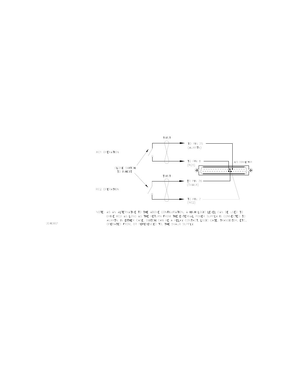
HSP power supplies incorporate two TTL-level inputs, RC1 and RC2, accessed via the I/O con-
nector, which can be used to disable the output regulator via external stimulus. These two con-
trols operate from an internal 5V supply (5VAUX) which is isolated from both input and output
(see PAR. 3.11), creating a “floating” inhibit control circuit which allows the user to control sev-
eral HSP power supplies operating at different return potentials from a single source. The two
control lines differ in that RC1 (pin 8) is normally high, initiating an output inhibit with application
of a low signal level, while RC2 (pin 7) is normally low and requires application of a high level
signal to inhibit the output; both of these signals are applied with respect to AUXRTN (see Fig-
ure 3-5), and can be operated at potentials as much as ±500V from the HSP output(s).
These two signal levels are TTL-compatible, both for voltage levels and source/sink capability. If
not actively driven, these signals have no effect on power supply operation. Activation of either
one of these control lines results in an immediate shutdown of the output PWM regulator, includ-
ing reset of the soft-start, undervoltage, and current walk-in circuits. Operation is inhibited until
the appropriate control line is released, whereupon the power supply output restarts as from ini-
tial cold turn-on.
FIGURE 3-5. REMOTE INHIBIT CONTROL OPERATION
An additional function which can be derived from the remote inhibit control circuitry is the ability
to reset the overvoltage/undervoltage latch circuitry without cycling the source power (Remote
Lockout Reset). When this function is enabled via switch S1-1, the latch can be reset by toggling
one of the inhibit control signals from enable to disable and back. The main advantages of this
remote reset function are the ability to reset the power supply from a remote location and an
instantaneous reset time (compared to the 30-second minimum waiting period imposed when
cycling the source power for reset).
3.13
MODULE CURRENT MONITOR
HSP power supplies provide a 0-5.5V analog signal named IMON, accessed via I/O connector
pin 32, which duplicates the signal level of the load sharing feedback signal (ISHARE) gener-
ated by each HSP. This permits the user to determine the load being provided by each module
within a parallel or redundant power system configuration. The IMON signal is current-limited