6 current limit programming range, 7 setpoint monitors, Current limit programming range -3 – KEPCO HSP Series Operator Manual User Manual
Page 29: Setpoint monitors -3, External voltage programming of current limit -3, R. 3.7)
HSPSERIES OPR 050614
3-3
ment down to near zero. The programming method is selected via S3 switch positions 2 and 3
as follows:
NOTE: One programming mode must be selected, or the HSP current limit programs to zero;
never select more than one programming mode at a time.
a)
Internal Programming: This is the factory-set (default) mode (see Figure 2-2); when
enabled via S3-3, the current limit is adjusted via the front panel potentiometer labeled
“I
MAX
” (see Figure 2-1).
b)
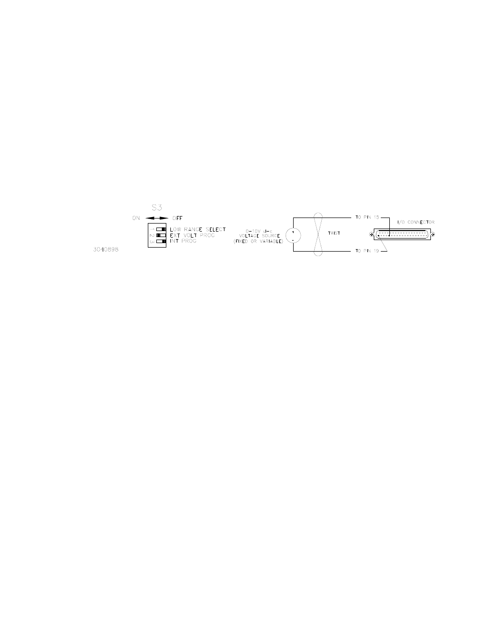
External Voltage Programming: When enabled via S3-2, this mode provides for current
limit adjustment via an external voltage source (0-10V) connected between pins 15 and
19 (IPROG, -S) of the I/O connector (see Figure 3-3). This technique is useful when
implementing digital control of the power supply current limit via a D/A converter; Kepco's
SN/SNR 488 programmers are ideally suited to these requirements.
FIGURE 3-3. EXTERNAL VOLTAGE PROGRAMMING OF CURRENT LIMIT
3.6
CURRENT LIMIT PROGRAMMING RANGE
The user may select the maximum programmable current limit, either high or low range, via S3
switch position 1 (see Figure 2-2). This permits the user to trade adjustment range for program-
ming resolution; this is especially useful when used in conjunction with external voltage pro-
gramming (see PAR. 3.5) for precise limit adjustment, or for limiting the maximum
programmable current limit. Operation of the range selector is as follows:
a)
High Range: This is the factory-set (default) mode; the maximum programmable current
limit is 110% of rated I
O
for all models.
b)
Low Range: When enabled via S3-1, the maximum programmable current limit is equal to
the rated output current I
O
for all models; since the programming voltage range does not
change, the resolution for a given programming input increment increases by 10%.
3.7
SETPOINT MONITORS
HSP power supplies provide measurement ports which permit the user to verify the pro-
grammed output voltage and current limit points while the power supply is in an active circuit,
and even when operated in a parallel/redundant configuration. These setpoint monitors access
the voltage and current loop reference sources to determine the programmed values, and con-
vert these reference levels to proportional voltages readable by the user. As the quantities mea-
sured are control circuit setpoints and not actual output measurements, the external operating
conditions do not influence these measurements and they remain valid even when the power
supply output is disabled; only valid source power is required.
The setpoints are available at two locations on the power supply. The first is via test probe jacks
on the front panel of the HSP, directly adjacent to their corresponding internal adjustment con-