RISCO Group ProSYS – ACM User Manual
Page 8
8
Advanced Communication Module
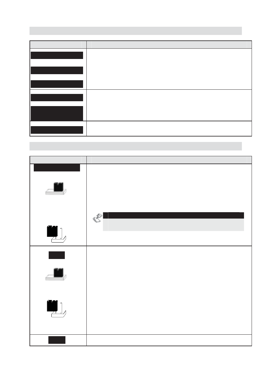
Terminal Block Wiring
Terminal
Description
AUX RED
COM BLK
BUS YEL GRN
Used to connect the ACM to the ProSYS Panel board
(the terminals are connected in parallel to the panel
BUS connector).
COM BLK
BUS 2 YEL2
GRN2
Provision for optional functionality
TIP, RING
Used for PSTN telephone line connection (for ACM
version that includes the modem option).
Jumper Settings
Jumper
Description
STAND ALONE
Used to enable a local U/D connection to the ProSYS
using a local PC, while the ACM is connected to the
BUS.
2 pins configuration: The ACM U/D channel is
disabled, and a local U/D connection to the ProSYS
Bus is enabled.
NOTE:
Sending information from the panel via the ACM is
functioning normally.
1 pin (default): Local U/D connection to the ProSYS
Bus is disabled, and the ACM channel is enabled.
DFLT
Used to restore the default software provided by the
manufacturer (e.g. when remote software upgrade
fails).
2 pins configuration: Enables restoring of the default
manufacturer’s software.
To restore the ACM to the default manufacturers
software:
1)
Disconnect power from the ACM
2)
Place the DFLT jumper on its 2 pins.
3)
Reconnect the power to the ACM.
1 pin (default): Restoring of the default
manufacturer’s software is not enabled.
CFG2
Provision for optional functionality