Multi-Contact MA221 User Manual
Page 7
7/8
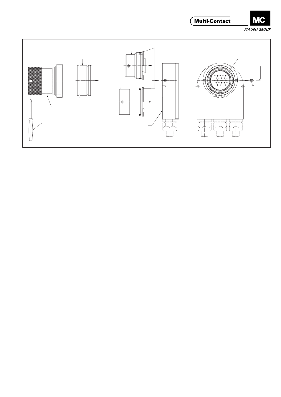
ill.15
5
9
1
9
7
8
2
10
6
(ill.15).
Die Kontakte werden von der
Steckseite her mittels Stiftausbau-
werkzeug (ill.4) bzw. Buchsenaus-
bauwerkzeug (ill.5) herausgedrückt.
Gewindestift (8) mit dem Sechskant-
Schraubendreher SW2 (7) heraus-
schrauben.
Das Stiftgehäuse- (1) bzw. Buchsen-
gehäuse-Vorderteil (2) mittels Mon-
tagering (5) und dem Schraubendreher
(6) als Drehebel aufschrauben. Danach
das Stiftgehäuse- (1) bzw. Buchsen-
gehäuse-Vorderteil (2) von Hand in
axialer Richtung abziehen. Das neue
Stiftgehäuse- (1) bzw. Buchsenge-
häuse-Vorderteil (2) lagerichtig (Nut
passend zu Führungsstift) einbauen
(von Hand eindrücken. Es ist unbe-
dingt darauf zu achten, dass das Stift-
(1) bzw. Buchsengehäuse-Vorderteil (2)
in das richtige, entsprechende
Gehäuse-Unterteil (10, siehe Aufschrift)
eingesetzt wird. Haltering (9) mittels
Montagering (5) wieder aufschrauben,
danach den Gewindestift (8) zur
Fixierung des Haltering's (9) mittels
Sechskant-Schraubendreher SW2 (7)
wieder einschrauben.
(ill. 15)
Press out the contacts from the
connection side with the pin extraction
tool (ill.4) or socket extraction tool (ill.
5). Remove the setscrew (8) with hex
key wrench A/F2 (7).
Unscrew front part of pin housing (1)
or socket housing (2) with the
assembly ring (5), turning with the
screwdriver (6) as a lever. Then, by
hand, pull off the pin (1) or socket (2)
housing front part in an axial direction.
Fit the new pin (1) or socket (2)
housing front part in the correct
position (slot in line with guide pin),
pressing in by hand. Check carefully
that the pin or socket housing front
part is fitted into the correct housing
lower part (10, see marking). Screw
the securing ring (9) back in place with
the assembly ring (5), then screw in
the setscrew (8) to fix the securing
ring (9) using a hex key wrench A/F 2
(7)
(ill.15)
Les contacts peuvent être extraits par la
face d'embrochage à l'aide de l'outil de
démontage adapté (ill.4 ou ill.5).
Dévisser l'embout fileté (8) à l'aide de la
clй а 6 pans 2 mm.
Dévisser le boîtier avant mâle (1) ou
femelle (2) à l'aide de la bague de
montage (5) et le tournevis (6) utilisé
comme levier). Tirer ensuite le boîtier
avant mâle (1) ou femelle (2) en
direction axiale à la main. Remonter le
nouveau boîtier avant mâle (1) ou
femelle (2) dans la position correcte
(rainure correspondant à la goupille de
guidage) (enfoncer à la main). Veiller
impérativement à mettre en place le
boîtier avant mâle (1) ou femelle (2) dans
le boîtier arrière qui lui correspond (10,
voir marquage). Revisser la bague de
fixation (9) au moyen de la bague de
montage (5), puis revisser l'embout
fileté (8) au moyen de la clй а 6 pans 2
mm (7) pour fixer la bague de fixation
(9).
Kleine Nut / small groove / petite rainure
www.multi-contact.com
Advanced Contact Technology