B60 schematics – MINOURA B60-R / B60-D User Manual
Page 3
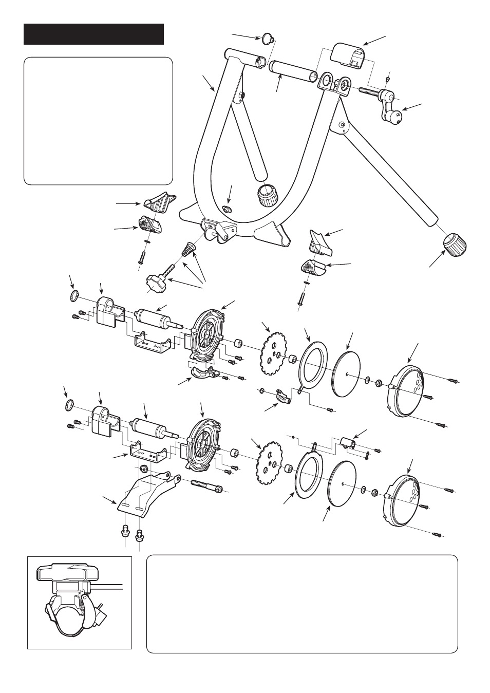
F-1: Coupling (Right)
F-4: Coupling Cover
F-7: Hub Handle
F-9: Grommet
BF-5: Leg Rubber Cover (White)
BF-6: Leg Rubber
BF-9: B60 Main Frame (Black)
BF-11: Plate Nut
M5-2: Rubber Foot Cap (29mm)
MF-3: Micro Adjust Knob Set
B60 Schematics
BF-9
BF-5
BF-6
M5-2
MF-3
F-7
F-4
F-9
F-1
EM-1
EM-2
EM-3
EM-4
EM-5
EM-6
EM-17
EM-8
EM-9
EM-10
EM-1
EM-2
EM-3
EM-4
EM-5
EM-12
EM-13
EM-17
EM-8
EM-11
LM-10
EM-1: Outer Cap
EM-10: Cable Guide
EM-2: Axle Holder
EM-11: Connecting Plate
EM-3: Drive Roller & Bearing
EM-12: Magnet Plate (Dial)
EM-4: Main Housing
EM-13: Dial Lever
EM-5: Alloy Plate
EM-17: Flywheel (600g)
EM-6: Magnet Plate (Remote)
GM-23: Remote Shifter
EM-8: Flywheel Cover
LM-10: Base Plate
EM-9: Remote Base
- Page 3 -
BF-5
BF-6
GM-23
BF-11
See also other documents in the category MINOURA For bicycles:
- LiveRide LR540 (8 pages)
- LiveRide LR960 (8 pages)
- LiveRide LR340 (8 pages)
- LiveRide LR240 (8 pages)
- RDA2429 (8 pages)
- Tablet Grip TPH-1 (2 pages)
- AC-Pro (4 pages)
- LiveRoll R700 (8 pages)
- MoZ-Roller (4 pages)
- MoZ-Roller (8 pages)
- MoZ-Roller (4 pages)
- BikeTower10 (4 pages)
- BikePit3 (4 pages)
- P-600AL-4 (6 pages)
- P-500AL-4 (8 pages)
- MPT-200S (4 pages)
- GravityStand2 (2 pages)
- Wheel Display Attachment 3 (2 pages)
- Bike Cradle 4 (2 pages)
- Bike Cradle 3 (2 pages)
- BC-V1 (2 pages)
- DS-4100 (2 pages)
- DS-4000 (2 pages)
- EBS-3 (4 pages)
- LEVEL-170H (2 pages)
- 971-3 (4 pages)
- 971-4 (4 pages)
- DS-2100 (4 pages)
- W-3100 (4 pages)
- W-150 (6 pages)
- RS-1600 (4 pages)
- Tancho DW-2 (4 pages)
- SS-700 (2 pages)
- HMS-10 (2 pages)
- FT-1 Combo (10 pages)
- FCG-310 (2 pages)
- HPS-9 “Get’A” (2 pages)
- True-Base (7 pages)
- MT-4000-SF (3 pages)
- Bike Rest ( Model : PHS-1 ) (2 pages)
- KingCarrier KCL-1F (3 pages)
- CS-500 (3 pages)
- CS-500 (2 pages)
- CS-500 (2 pages)