Opening the interface cover, Extron rgb 168xi – Extron Electronics RGB 168xi User Manual
Page 18
RGB 168xi
xi
xi
xi
xi • Installation and Operation
Installation and Operation, cont’d
Setting Internal Jumpers
The jumpers inside the interface(s) are set at the factory to meet
the requirements of most systems. However, you can
change a jumper setting to meet the needs of a particular
system.
Changes to internal jumper settings must be
performed by authorized service personnel only.
The user-configurable, internal jumpers control the
following functions:
• horizontal and vertical sync polarity, and
• vertical sync pulse width.
Follow these steps to change the jumper settings.
1
. Remove power from the interface (if it is connected) by
disconnecting the AC power cord from the unit.
2
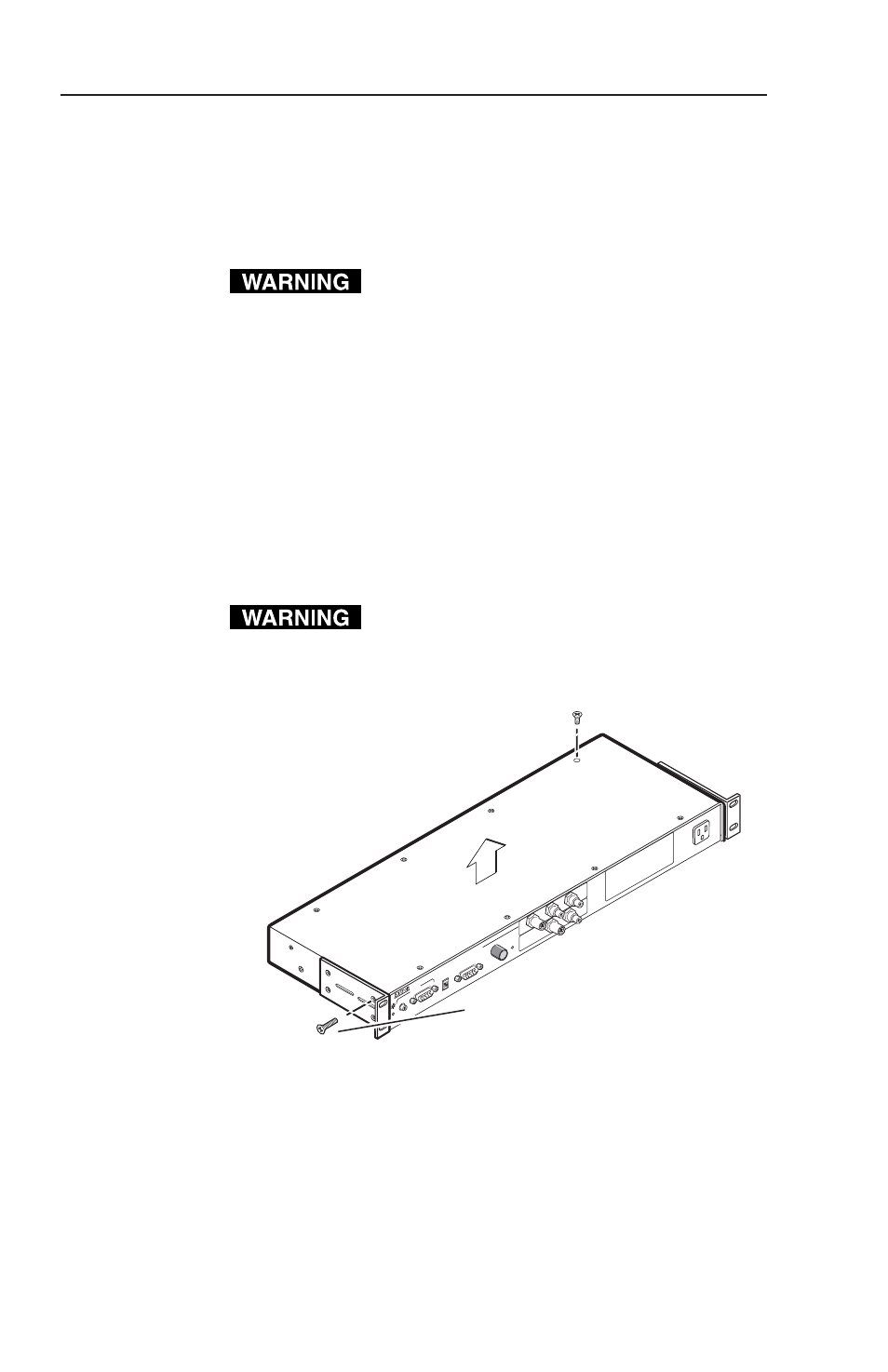
. Open the cover of the interface (the top half of the
enclosure), as shown below.
Do not touch any switches or electronic
components inside the interface. Doing so
could damage the interface.
Opening the interface cover
3
. Note the positions of jumpers J20 and J40 before
changing jumper settings. The following illustration of
the circuit board shows the locations of the J20 and J40
jumpers. There are two possible setting combinations
for 3-pin jumpers:
Extron
RGB 168xi
RGB 168 xi
INPUTS
AU
DIO
ANALOG
UNSWITCHED
600 W
ATTS
MAX.
MIN/MAX
UNIVERSAL INTERF
ACE
W /ADSP
ID PIN 14
ID PIN 11
BUFFERED LOCAL
MONIT
OR OUTPUT
Remove #8 Screw
(4 Plcs) Each Side
and Bracket, if Present
Remove (12)
Screws
Lift Cover
Straight Up
2-8