Front panel, Analog video input 15-pin hd female connector – Extron Electronics RGB 168xi User Manual
Page 13
RGB 168xi
xi
xi
xi
xi • Installation and Operation
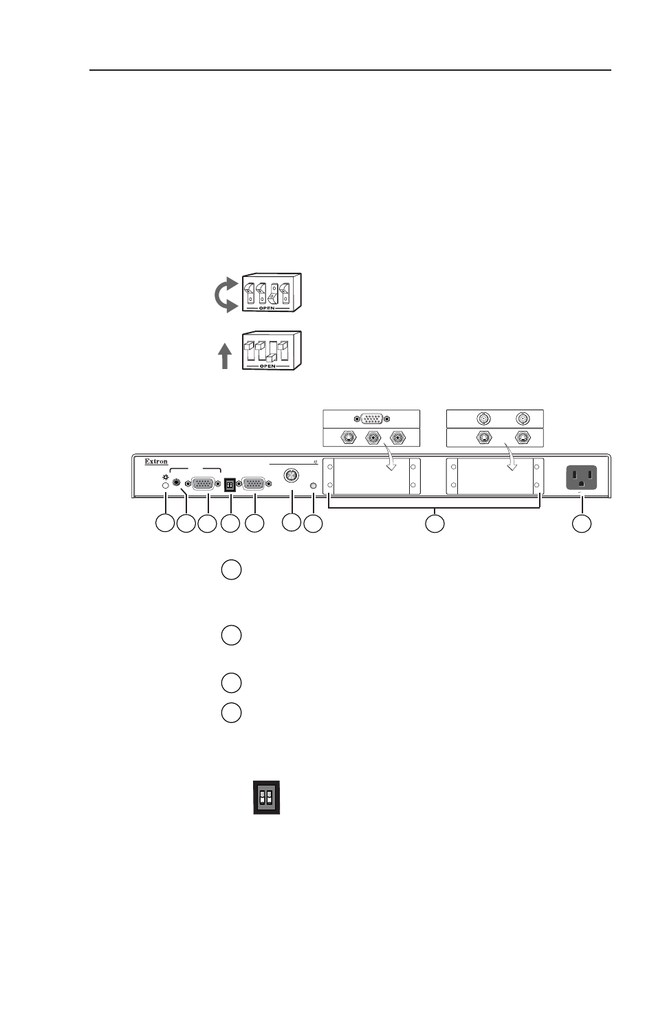
Front Panel
This section familiarizes you with the front panel features
and the options for making connections and changing
settings.
Setting DIP switches
The DIP switches on the front and rear panels of the
RGB 168xi may be either the rocking type or the sliding
type.
To set rocking type DIP switches, use a
small screwdriver to depress the
appropriate end of each switch.
To set sliding type DIP switches, use a small
screwdriver to slide (push) the switch to the
On/closed or Off/open position.
1
2-color power/signal LED
— This LED lights amber
to indicate power on only. It lights green to indicate
that power is on and a video signal is also present.
2
Audio input jack
— This 3.5 mm stereo input jack
accepts an unbalanced stereo audio input.
3
Analog video input 15-pin HD female connector
4
ID bit termination DIP switches
— These switches
provide proper ID bit termination when a local
monitor is not connected to the interface’s
buffered local monitor output.
DIP switch 1 connects pin 4 to ground.
DIP switch 2 connects pin 11 to ground.
ON — Set both switches (ID PIN 4 and
ID PIN 11) to On if no local monitor is
connected.
OFF — Set both switches to Off if a local
monitor is attached to the interface.
3
4
1
2
3
4
1
2
2-3
ID PIN 4
ID PIN 11
UNSWITCHED
100-240 0.5A MAX.
RGB 168
H. SHIFT
MIN/MAX
INPUTS
AUDIO
ANALOG
BUFFERED LOCAL
MONITOR OUTPUT
UNIVERSAL INTERFACE W/ADSP
ID PIN 4
ID PIN 11
1
3
5
7
8
9
2
6
4