Rear panel – Extron Electronics RGB 168xi User Manual
Page 15
RGB 168xi
xi
xi
xi
xi • Installation and Operation
2-5
3
SOG
DDSP
SERR
SPARE
100-240 50/60 Hz 0.5A
OUTPUT
R
H
G
V
B
S
UNITY
50%
100%
GAIN/
PEAK
1
2
5
7
2
6
4
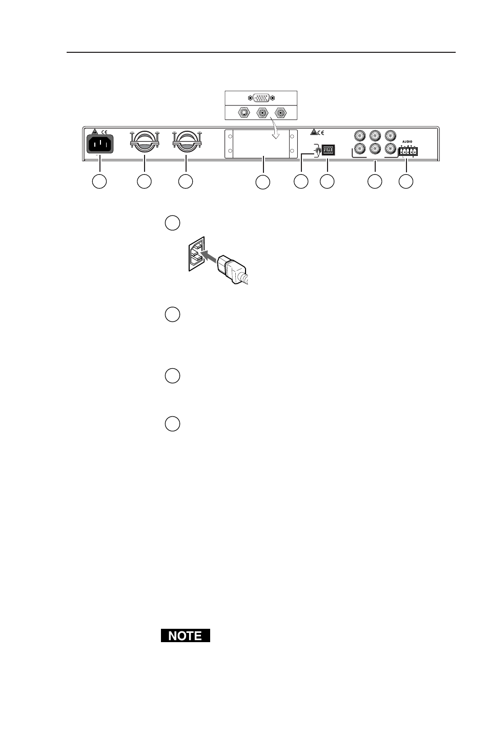
Rear Panel
1
AC power input connector
— Connect a standard
IEC AC power cord here for power
input (100 VAC to 240 VAC, 50/60 Hz).
2
Cable access openings
— Cables attached to the
front panel A/V pass-through architectural adapter
plates exit the enclosure here. Clamp cables in place
with the supplied hardware.
3
Optional output architectural adapter plate
— Front
panel input AAP A/V connectors can be wired here
to pass-through output connectors.
4
3-position gain/peaking switch
— Use this toggle
switch to compensate for signal degradation caused
by long (over about 125 feet) cable lengths. Choose
the setting that provides the best image on the
output display device. Select from these options:
• Unity (no gain or peaking) — The output level is
the same as that of the input and with no
added peaking.
• 50% — This setting increases the output signal
level and adds 50% of the maximum peaking
to the signal.
• 100% — This setting increases the output signal
level and adds 100% of the maximum peaking
to the signal.
If the signal cable between the interface and the
display device is shorter than 125 feet, and the gain/
peak switch is set to a setting other than unity, the
image may be overly bright (overcompensated).