2 installation, 1 mechanical installation, 2 slot selection – Emerson P/N 400361-00 User Manual
Page 17: 3 electrical connections, 4 digital i/o connections
Installation www.emersonct.com 3
2 Installation
This section of the manual will cover basic installation
information.
2.1 Mechanical Installation
Please refer to the Installation Sheet that comes with the
SM-EZMotion module for details on installing the module
into the Unidrive SP.
2.2 Slot Selection
The SM-EZMotion module may be placed in any of the
three available option slots on the Unidrive SP. The user
must indicate which slot the SM-EZMotion is fitted in using
PowerTools Pro configuration software. The default slot
number is Slot 3 in the configuration software.
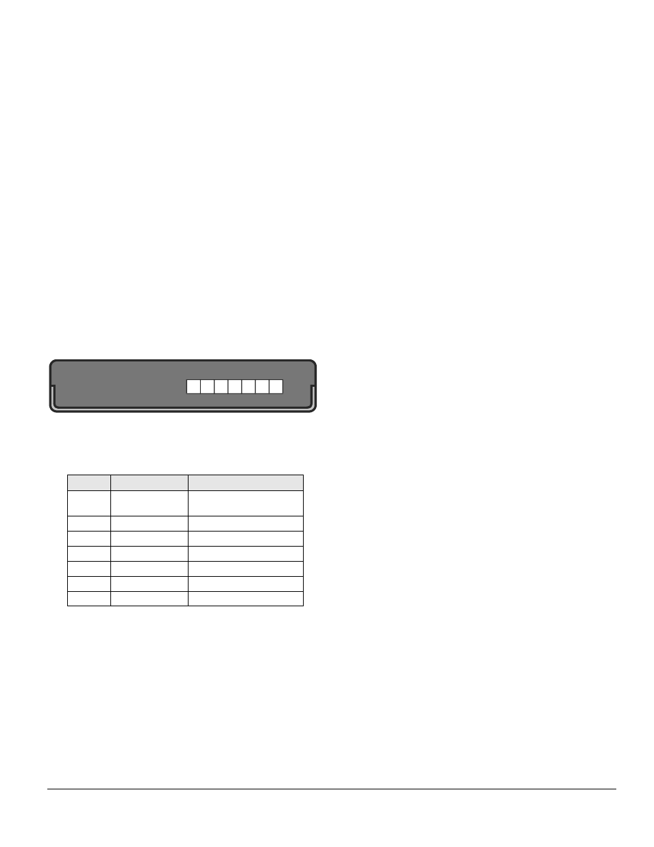
2.3 Electrical Connections
The SM-EZMotion module has three separate terminal
blocks used to access the different features. Figure 2
shows a diagram of these connections.
Figure 2:
Connection Diagram
The terminals are numbered from Terminal 1 on the left to
Terminal 7 on the right. The different terminal functions are
listed in the table below.
2.4 Digital I/O Connections
The SM-EZMotion module is equipped with 4 digital inputs
and 2 digital outputs. The I/O are electrically sourcing I/O.
All I/O utilize positive logic meaning that they are active
when positive voltage is applied (10-30 VDC). See the
Specifications section at the back of the manual for more
detailed information on the digital I/O.
These digital I/O can be used to control different functions
in the SM-EZMotion module. The digital I/O on the
SM-EZMotion are updated at the SM-EZMotion Trajectory
Update Rate. The Trajectory Update Rate can be found on
the Setup view in PowerTools Pro (see “Setup View” on
page 37 for more information on the Trajectory Update
Rate).
The digital I/O on the SM-EZMotion module are also
unique (as compared to Unidrive SP digital I/O and SM-I/O
Plus module I/O) because they can be used in the
SM-EZMotion high speed capture process. Even though
they are only updated once every Trajectory Update, the
SM-EZMotion processor knows when they activate to
within 1 microsecond. Therefore, when Capture is used,
they can be accurate to 1 microsecond (see “Capture
View” on page 46 for more information on the
SM-EZMotion Capture object).
2.5 Connecting Motor Encoder
Feedback to the Unidrive SP
Figure 3 can be used to connect the encoder feedback
signals for various different motors to the Unidrive SP. For
further installation information, please refer to the Unidrive
SP User Guide.
Terminal #
Function
Description
1
OV Common
OV Common connection for
digital I/O
2
Input1
Digital Input 1
3
Input2
Digital Input 2
4
Input3
Digital Input 3
5
Input4
Digital Input 4
6
Output1
Digital Output 1
7
Output 2
Digital Output 2
1
2 3 4
5
6
7