Figure 3 main display screen, typical, Figure 4 mimic display, Figure 3 – Emerson 250-400kVA User Manual
Page 12: Main display screen, typical, Figure 4, Mimic display
Operation
6
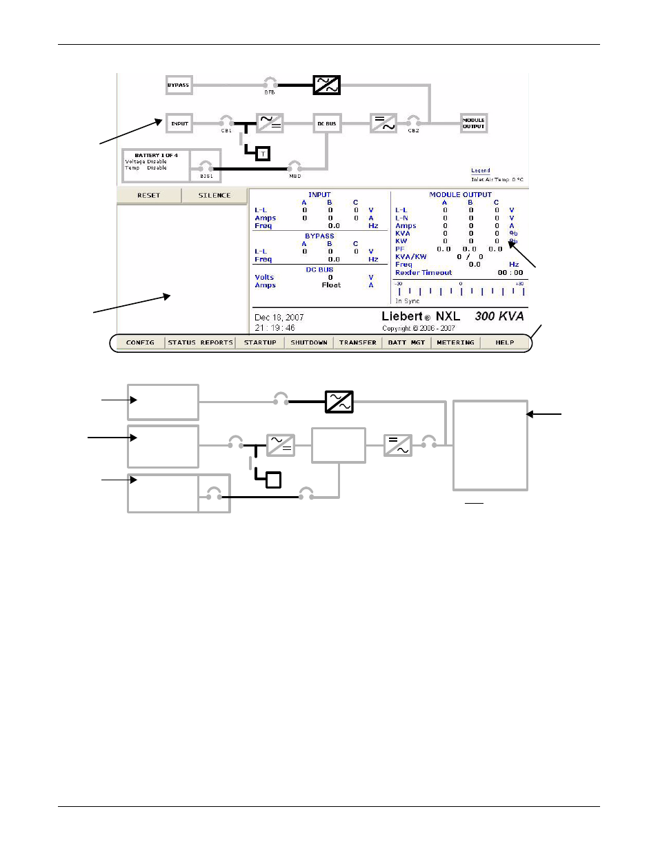
Figure 3
Main Display Screen, typical
Figure 4
Mimic display
Bypass Input—Displays the bypass input voltage and the bypass input frequency. The bypass cir-
cuit breaker (BFB) is to the right of this block. The circuit breaker status is shown as open or closed.
UPS Input Power—Displays the UPS input voltage, current and frequency. The input circuit
breaker (CB1) is to the right of this block. The circuit breaker status is shown as open or closed.
Battery Block—Displays the battery voltage and the charge or discharge current to or from the bat-
tery. Pressing this icon switches among the connected battery strings. The Module Battery Discon-
nect (MBD) is to the right of this block. The circuit breaker status is shown as open or closed.
DC Bus—Displays the DC Bus voltage and the state of the battery charger.
Load—Displays the output line voltage, phase voltage, current, kVA, kW, power factor and fre-
quency. The critical load current per phase is also displayed in this block. During an overload, the
time remaining before transfer is displayed at the bottom of the load box. After an overload transfer,
retransfer timeout is displayed at the bottom of the load box.
Mimic
Display
Active
Event
Window
Multipurpose
Display
Menu
Bar
INPUT
A
B
C
L-L
0
0
0
V
I
0
0
0
A
Freq
0.0Hz
BATTERY 1 OF 4
Voltage Disable
Temp
Disable
T
BYPASS
A
B
C
L-L
0
0
0
V
Freq
0.0Hz
Voltage
0V
Current Float
CB1
BFB
MBD
BIS1
CB2
Legend
Inlet Air Temp 0°C
A
B
C
L-L
0
0
0
V
L-N
0
0
0
V
I
0
0
0
A
KVA
0
0
0
%
KW
0
0
0
%
PF
0.0
0.0 0.0
KVA/KW
0/
0
Freq
0.0Hz
Rexfer Timeout
00:00
MODULE OUTPUT
DC BUS
Bypass
Input
UPS
Input
Power
Battery
Block
Load