Appendix b – battery information – Magnum Energy MMS Series User Manual
Page 48
© 2014 Magnum Energy, Inc.
Appendix B – Battery Information
42
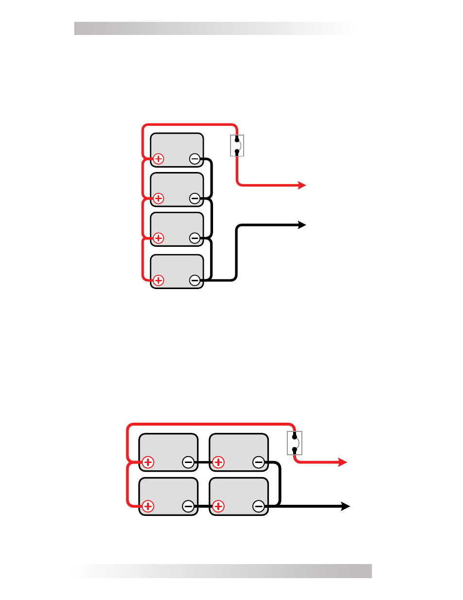
Figure 21, Series-Parallel Battery Wiring
overcurrent
protection
String 2
String 1
12 volt battery bank (total capacity = 400 AHrs)
To
12 VDC
Inverter
6 volts
(200 AHrs)
6 volts
(200 AHrs)
6 volts
(200 AHrs)
6 volts
(200 AHrs)
(First)
(Last)
Series-Parallel Wiring
–
A series-parallel confi guration increases
both voltage (to match the inverter’s DC requirements) and capacity
(to increase run time for operating the loads) using smaller, lower-
voltage batteries. In the example below (Figure 21), four 6 VDC/200
AHr batteries are combined into two strings resulting in a 12 VDC/400
AHr battery bank.
Figure 20, Parallel Battery Wiring
12 volt battery bank (total capacity = 400 AHrs)
overcurrent
protection
12 volts
(100 AHrs)
12 volts
(100 AHrs)
12 volts
(100 AHrs)
12 volts
(100 AHrs)
To
12 VDC
Inverter
Parallel Wiring
–
Wiring the batteries in parallel increases the total
run time the batteries can operate the AC loads. A parallel connection
combines overall battery capacity by the number of batteries in the
string. Even though there are multiple batteries, the voltage remains
the same. In the example below (Figure 20), four 12 VDC/100 AHr
batteries are combined into a single 12 VDC/400 AHr battery bank.