Installation, Inverter model – Magnum Energy MMS Series User Manual
Page 21
© 2014 Magnum Energy,
Inc.
Installation
15
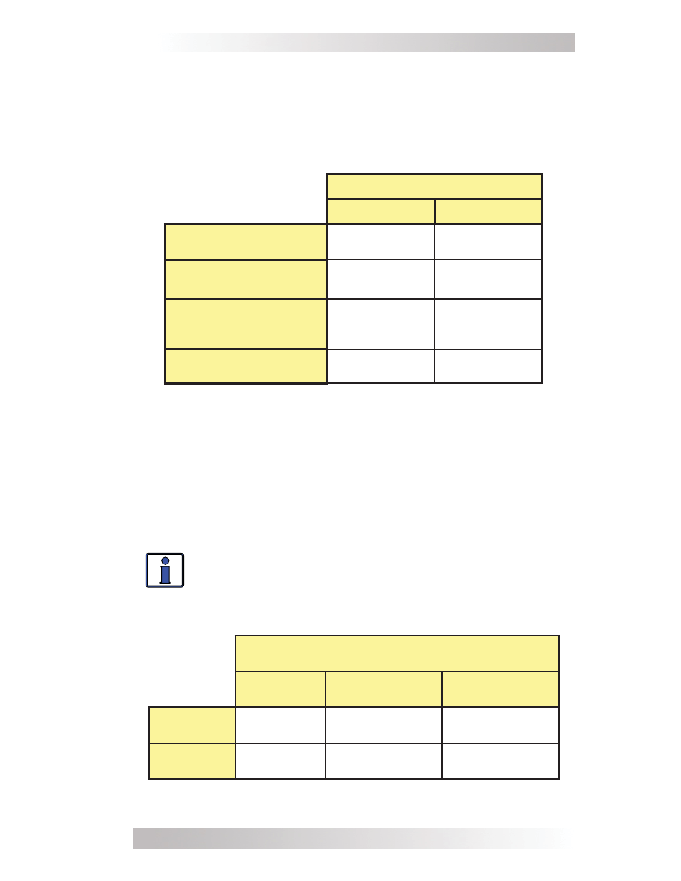
Table 1, Recommended DC Wire/Overcurrent Device
Info: The term “in free air” is defi ned by the NEC as not
encased in conduit or raceway.
Note¹ – Maximum Continuous Current is based on the inverter’s continuous
power rating at the lowest input voltage with an ineffi ciency factor.
Note² – Per the NEC, the DC grounding electrode conductor can be a #6
AWG conductor if that is the only connection to the grounding electrode and
that grounding electrode is a pipe, rod, or plate electrode.
Note³ – Wire size is based on the requirements needed to increase effi ciency
and reduce stress to the inverter.
Note – The next larger standard size overcurrent device may be used if
the de-rated cable ampacity falls between the standard overcurrent devices
found in the NEC.
Inverter Model
MMS1012
MMS1012-G
Maximum Continuous
Current¹
133 amps
133 amps
DC Grounding
Electrode Wire Size²
#6 AWG
(13.3 mm²)
#6 AWG
(13.3 mm²)
Minimum DC Wire Size³
(75˚C rating in free air)
#2 AWG
(33.6 mm²)
[170 amps]
#2 AWG
(33.6 mm²)
[170 amps]
Maximum DC Fuse Size
150 amps with
time delay
150 amps with
time delay
Table 2, DC Wire Size For Increased Distance
Minimum recommended DC wire size (one way)
5 ft or less
(≤1.5 m)
5 to 10 ft
(1.5 m - 3.0 m)
10 to 15 ft
(3.0 m - 4.6 m)
MMS1012
#2 AWG
(33.6 mm²)
#2 AWG
(33.6 mm²)
#1 AWG
(42.4 mm²)
MMS1012-G
#2 AWG
(33.6 mm²)
#2 AWG
(33.6 mm²)
#1 AWG
(42.4 mm²)
rated. It must be correctly sized according to the size of DC cables
being used, which means it is required to open before the cable
reaches its maximum current carrying capability, thereby preventing
a fi re.
See Table 1 to select the DC overcurrent device based on the
minimum wire size for your inverter model.