4 ac input wiring, Installation – Magnum Energy MMS Series User Manual
Page 28
© 2014 Magnum Energy, Inc.
2.4.4 AC Input Wiring
Your inverter has an AC transfer feature that passes the AC input
power to the inverter’s output. Connection to the AC input is made
by hardwiring from a distribution panel as described below:
1. Run an appropriately sized 2-conductor plus ground cable (from
the AC distribution panel) through the strain relief clamp on the AC
IN opening (Figure 3, Item 10). Refer to Table 4 for minimum wire
size and overcurrent protection required for the AC input wiring.
2. Remove about two inches of the insulating jacket from the AC
cable, and then separate the three wires and strip about 3/4”
(1.9 cm) of insulation from each wire.
3. Using approved AC wire connectors, connect the incoming Hot
In, Neutral In, and Ground wires to the MMS Series’ AC wires
colored black (HOT IN), white (NEUT IN), and green (AC GROUND)
respectively.
4. After making the AC input connections, secure the AC input cable
by tightening the strain relief clamp.
The AC input wiring in the inverter is complete. Review all AC wiring
to ensure all connections are correct and secure.
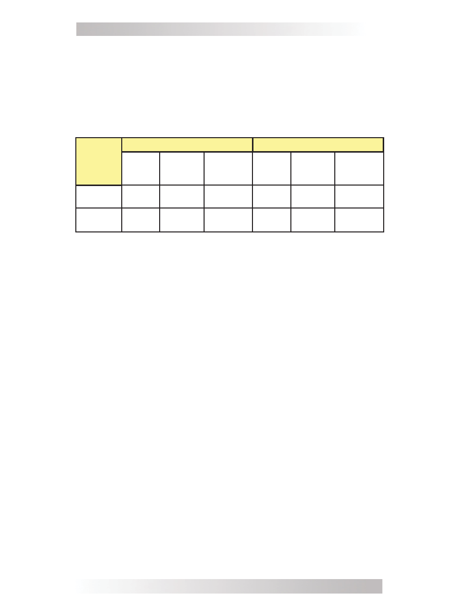
Table 4, Minimum Wire Size to Circuit-breaker Size
Based on information from the NEC, Table 4 provides the minimum
AC wire size and the suggested breaker size based on inverter model.
H
owever, a larger wire size may be required because of voltage drop.
The
AC wire sizes provided in this table assume using only copper
wire and a temperature rating of 75°C (167°F) or higher. A minimum
of #14 AWG
(2.1 mm²)
is required for all AC wiring.
22
Installation
Inverter
Model
AC Input
AC Output
Input
Breaker
Minimum
Wire
Size
Suggested
Breaker
Size
Output
Breaker
Minimum
Wire
Size
Suggested
Breaker
Size
MMS1012
20
amps
#12
AWG
(3.3 mm²)
20
amps
15
amps
#14
AWG
(2.1 mm²)
15
amps
MMS1012
-G
20
amps
#12
AWG
(3.3 mm²)
20
amps
15
amps
#14
AWG
(2.1 mm²)
15
amps