Magnum Energy MMS Series User Manual
Page 10
© 2014 Magnum Energy, Inc.
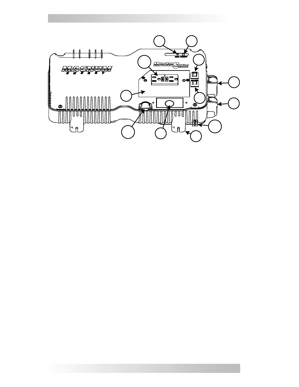
Figure 3, Top and Left Side Features
1. Inverter Status Indicator – a green LED that illuminates to
provide information on the inverter’s operation.
2. Power
Switch
– a momentary pushbutton switch that turns the
inverter on or off.
3. Negative DC Terminal (black) – the inverter’s connection to
the negative terminal on the battery bank.
4. Positive DC Terminal (red) – the inverter’s connection to the
positive terminal on the battery bank.
5. Input Circuit Breaker – a circuit breaker that protects the unit’s
internal wiring and pass-thru relay.
6. Output Circuit Breaker – a circuit breaker that provides another
layer of overload protection. Not a branch circuit-rated breaker.
Separate AC output breakers may be required on the output.
7. Mounting Flanges (x4) – secure the inverter to shelf/wall.
8. AC
Wiring
Compartment
- provides access for all AC input and
output connections on the inverter.
9. AC Output Connection – AC knockout for hardwiring AC output.
10. AC Input Connection
– a strain relief clamp for hardwiring AC
input. The strain relief comes with an attached fl exible AC input
power cord on the MMS1012-G model.
11. DC Ground Terminal – a connection that is used to tie the
exposed chassis of the inverter to the DC grounding system. This
terminal accepts CU/AL conductors from #14 AWG (2.1 mm²) to
#6 AWG (13.3 mm²).
12. GFCI Outlet – Ground Fault Circuit Interrupter outlet (with test
and reset capability). Only available on MMS1012-G model.
4
Introduction
1
2
3
4
5
6
7
8
10
9
11
12