3 wiring guidelines, Installation – Magnum Energy MMS Series User Manual
Page 19
© 2014 Magnum Energy,
Inc.
2.1.3 Wiring
Guidelines
• Before connecting any wires, determine all wire routes to and
from the inverter throughout the RV, vehicle, or boat.
• Conductors passing through walls or other structural members
must be protected to minimize insulation damage such as chafi ng,
which can be caused by vibration or constant rubbing.
• Always check for existing electrical, plumbing, or other areas of
potential damage prior to cutting into structural surfaces or walls.
• Make sure all wires have a smooth bend radius and do not be-
come kinked.
• Both AC and DC overcurrent protection must be provided as part
of the installation.
• Do not attempt to use a vehicle metal frame in place of the nega-
tive connection or DC ground. The inverter requires a reliable
negative and ground return path directly to the battery.
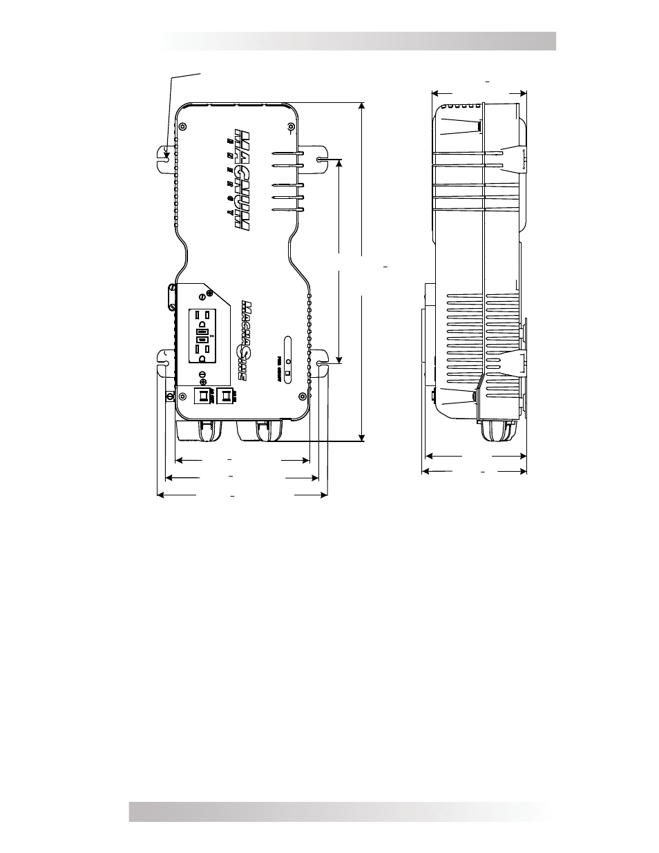
Figure 10, MMS1012-G Model Inverter/Charger Dimensions
Installation
~ 16 "
(16.59")
~ 6 " (6.71")
10"
~ 5 "
(5.125")
~ 4 "
(4.625")
~ 5"
Mounting holes x4
[
¼” (0.25") diameter]
~ 7 " (7.51")
~ 8 " (8.41")
5
8
5
8
1
8
7
16
1
2
3
4
13