Installation – Magnum Energy MMS Series User Manual
Page 18
© 2014 Magnum Energy, Inc.
12
Installation
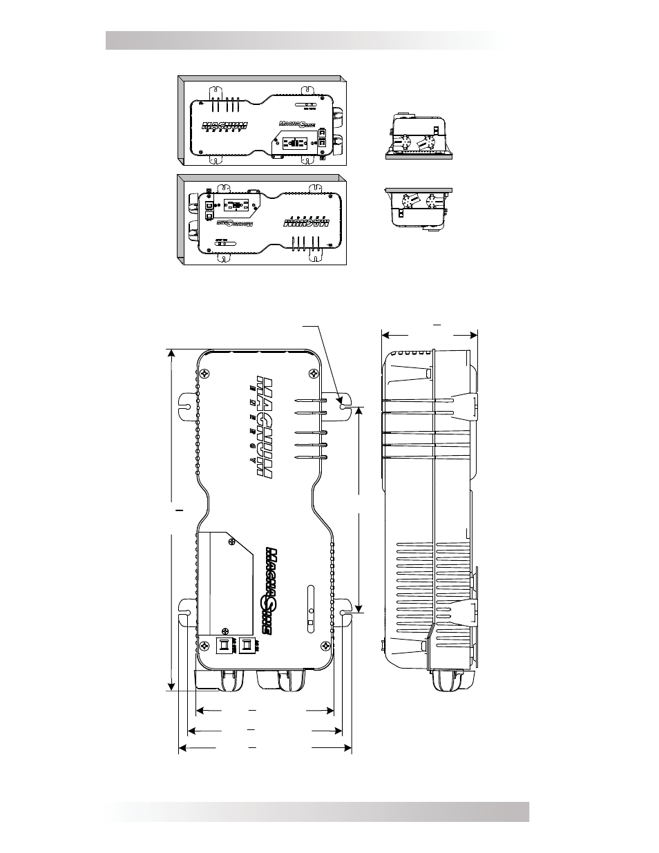
Figure 9, MMS1012 Model Inverter/Charger Dimensions
Mounting holes x4
[¼” (0.25") diameter]
10.0"
~ 16 "
(16.59")
~ 6 " (6.71")
~ 8 " (8.41")
~ 7 " (7.51")
~ 4 "
(4.625")
3
4
7
16
1
2
5
8
5
8
Shelf Mounted
(right-side up)
Shelf Mounted
(up-side down)
Wall Mounted (up-side down)
Wall Mounted (right-side up)
Figure 8, Approved MMS1012 (-G) Mounting Orientations
See also other documents in the category Magnum Energy Relay:
- MM Series (44 pages)
- MM-E Series (48 pages)
- RD-E Series (58 pages)
- ME Series (68 pages)
- MSH-RE Series (76 pages)
- MSH-M Series (64 pages)
- ME-MR Remote (47 pages)
- MMS-E Series (51 pages)
- ME-G Series (62 pages)
- MS-PE Series (64 pages)
- MS-G Series (74 pages)
- MS-AEJ Series (52 pages)
- ME-ARC Remote (2 pages)
- ME-ARC Remote (4 pages)
- ME-ARC Remote (107 pages)
- ME-ARC Remote (139 pages)
- ME-RTR Router (3 pages)
- ME-RTR Router (135 pages)
- ME-RC Remote (87 pages)
- DC Load Disconnect (ME-DCLD) (2 pages)
- MM-RC Remote (16 pages)
- DC Load Disconnect (MM-DCLD) (2 pages)
- GFCI Outlet (MS-GFCI) (4 pages)
- Ignition Switch Activate (MM-ISA) (2 pages)
- Ignition Switch Lockout (MM-ISW) (2 pages)
- Pigtail Adapters ME-PT1 (2 pages)
- Remote Bezel (ME-RC-BZ) (2 pages)
- Pigtail Adapters ME-PT2 (2 pages)
- Remote Switch Adapters ME-RSA (2 pages)
- Remote Switch Adapters ME-RSA-M (2 pages)
- Series Stacking Cable Kit (ME-SSI) (28 pages)