Bump test, Ingress of water, Ptfe filter disc (871026) – Ion Science Cub User Manual
Page 35
CUB MANUAL
Ion Science Ltd
Page 35 of 42
Unrivalled Detection. www.ionscience.com
Maintenance
On the Cub
’s page, click on this button for the Cub being calibrated: The calibration procedure is
then initiated. The Calibration dock then pumps Zero gas and then Span gas to the sensor. If the
calibration is successful a date time stamp will be shown in the calibration summary box. If the
calibration fails the
message “Invalid” appears on the Cub’s page. If a calibration is invalid the Cub
will revert to the previous calibration.
Bump Test
To carry out a bump test on a Cub, apply the gas as described above, and click this button on the
Cub
’s page for the Cub in question: The bump test is then carried out. The gas is applied and the
test checks that the output reaches the levels specified in the preferences (see Configuring a
Cub).
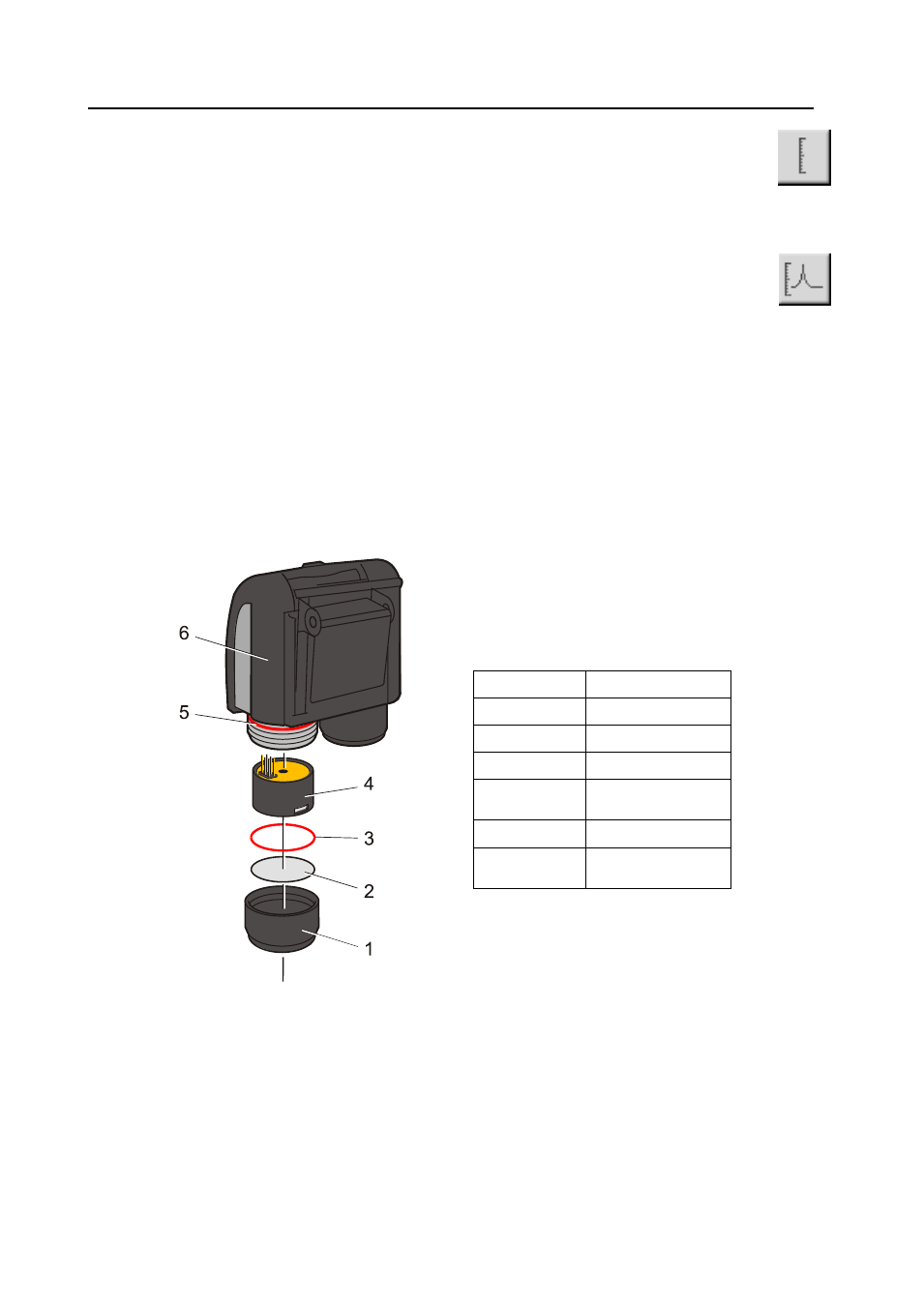
Ingress of Water
If the Portable Cub has been subject to a deluge of water then it is necessary to shake the Cub vigorously to
remove entrapped water from underneath the protective gauze lying above the filter located over the gas
sensor. To ensure there is no impeding of gas through the filter to the gas filter replace, with new, the Filter
Disc (2) and O Ring (3). (See below).
PTFE Filter Disc (871026)
The Filter Disc (2) should be changed after every 100 hours of use. This frequency should be increased for
dusty or moisture laden environments or whenever the filter appears ‘dirty’ when viewed by removing the
Sensor Cover. Filter Disc changing should be conducted in a suitably clean environment, with clean hands
and equipment to avoid contamination of the new Filter Disc.
Item Number
Part Number
1
A-871027
2
871026
3
5/OO-108
4
(Multiple variants
available)
5
5/OO-110
6
(Mulitple variants
available)
To change the Filter Disc (2), unscrew the Sensor Cover (1), and tap the Sensor Cover onto a suitable clean
surface to dislodge the O Ring (3) and Filter Disc (2). Carefully place a new Filter Disc (2) in first and O Ring
(3) in second into the Sensor Cover. (Under no circumstances should a Filter Disc and O Ring be used
once it has been removed.) Make sure that O Ring (5) has remained in position. Then ensuring the Filter
Disc (2) and O Ring (3) are correctly positioned, screw the Sensor Cover (1) onto the Instrument Body (6).
Do not over-tighten.