Network cable is connected correctly, Run/stop operation parameter is set correctly, Frequency reference parameter is set correctly – Yaskawa Profibus-DP Option Card CM061 User Manual
Page 58: Troubleshooting d-6
Troubleshooting D-6
#
Network Cable Is Connected Correctly
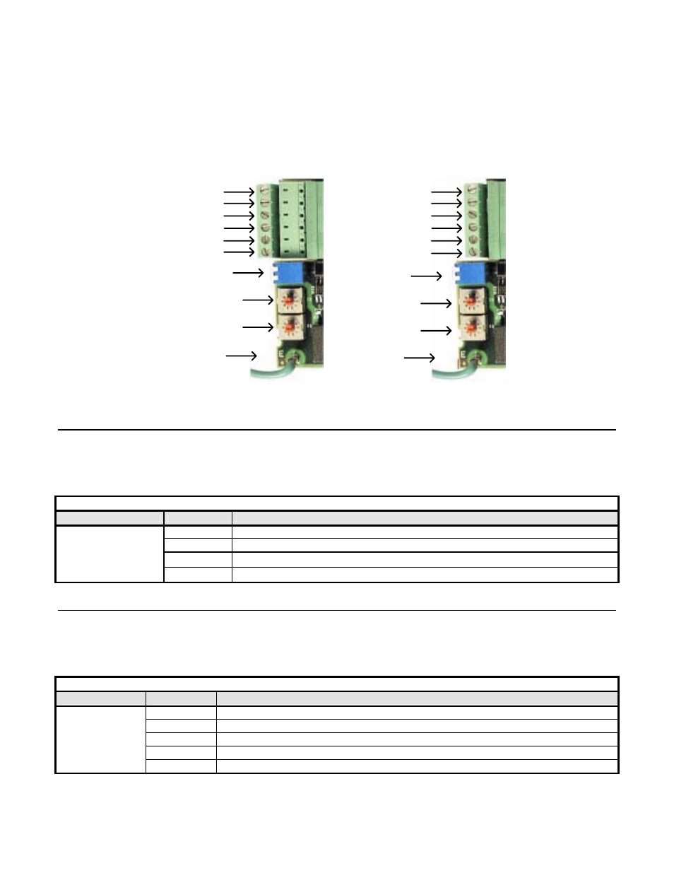
! Determine the type of connector on the PROFIBUS-DP Option. Connector Style A is an extended Phoenix connector. The
extension can be seen on the back of the connector as a small circuit board. Connector Style B is a standard phoenix connector
without any modifications.
! Connect the PROFIBUS-DP network cable to the PROFIBUS-DP Option. Refer to the appropriate connection drawing in Figure
C.2 below for your connector style.
! Use standard PROFIBUS-DP cable as specified by the PROFIBUS Organization.
C
o
n
n
e
c
to
r
S
ty
le
A
Reserved
Shield
1
B Out (RED)
4
5
6
Ground
A In (Green)
2
B In (RED)
A Out (Green)
3
C
o
n
n
e
c
to
r
S
ty
le
B
Reserved
Shield
1
2
A In/Out (Green)
3
B In/Out (RED)
4
5
6
Reserved
Reserved
Ground
Termination
S2
S1
Termination
S2
S1
Figure D.1 – PROFIBUS-DP Option Connections
#
Run/Stop Operation Parameter Is Set Correctly.
Parameter b1-02 needs to be set to the source of the drive’s Run/Stop command. If the receives the Run/Stop command from the
PROFIBUS-DP network, parameter b1-02 must be set to “3 – Option PCB”. Refer to the appropriate drive technical manual for further
explanation of this parameter.
Table D.1 - Run/Stop Reference Source
Parameter
Value
Description
0
Operator Keypad
1 External
Terminals
2 Serial
Communications
b1-02
3
Option PCB (PROFIBUS-DP Communications)
#
Frequency Reference Parameter Is Set Correctly
Parameter b1-01 needs to be set to the source of the drive’s frequency reference command. If the receives its frequency reference from the
PROFIBUS-DP network, parameter b1-01 must be set to “3 – Option PCB”. Refer to the appropriate drive technical manual for further
explanation of this parameter.
Table D.2 - Frequency Reference Source
Parameter
Value
Description
0 Operator
keypad
1 Terminals
2 Serial
Communications
3
Option PCB (PROFIBUS-DP Communications)
b1-01
4
Pulse input (Available on F7 and G7 drives only)