6 word input/output message, Fast i/o output data, Network communications 3-7 – Yaskawa Profibus-DP Option Card CM061 User Manual
Page 31
Network Communications 3-7
6 Word Input/Output Message
The 6 word input and output messages are divided into two areas. The first 4 bytes of each message is fixed. This is the most frequently
used data and is referred to as the fast I/O data. The remaining 8 bytes of each message are used for reading from and writing to all other
drive registers and is referred to as parameter data. All command, monitor, and parameter data in the drive is accessible via the Parameter
Access portion of the message. . Note: Care must be taken when writing certain parameters to the drive as other parameters may be
dependant on them. Control method, A1-02, maximum Frequency, E1-04, and Acc/Dec Scale Time, C1-10, are just a few. Refer to the
appropriate drive MODBUS
technical manual for more information.
The 6 word input and output messages was designed for situations where processor memory may be a factor in the number of PROFIBUS-
DP devices resident on the network.
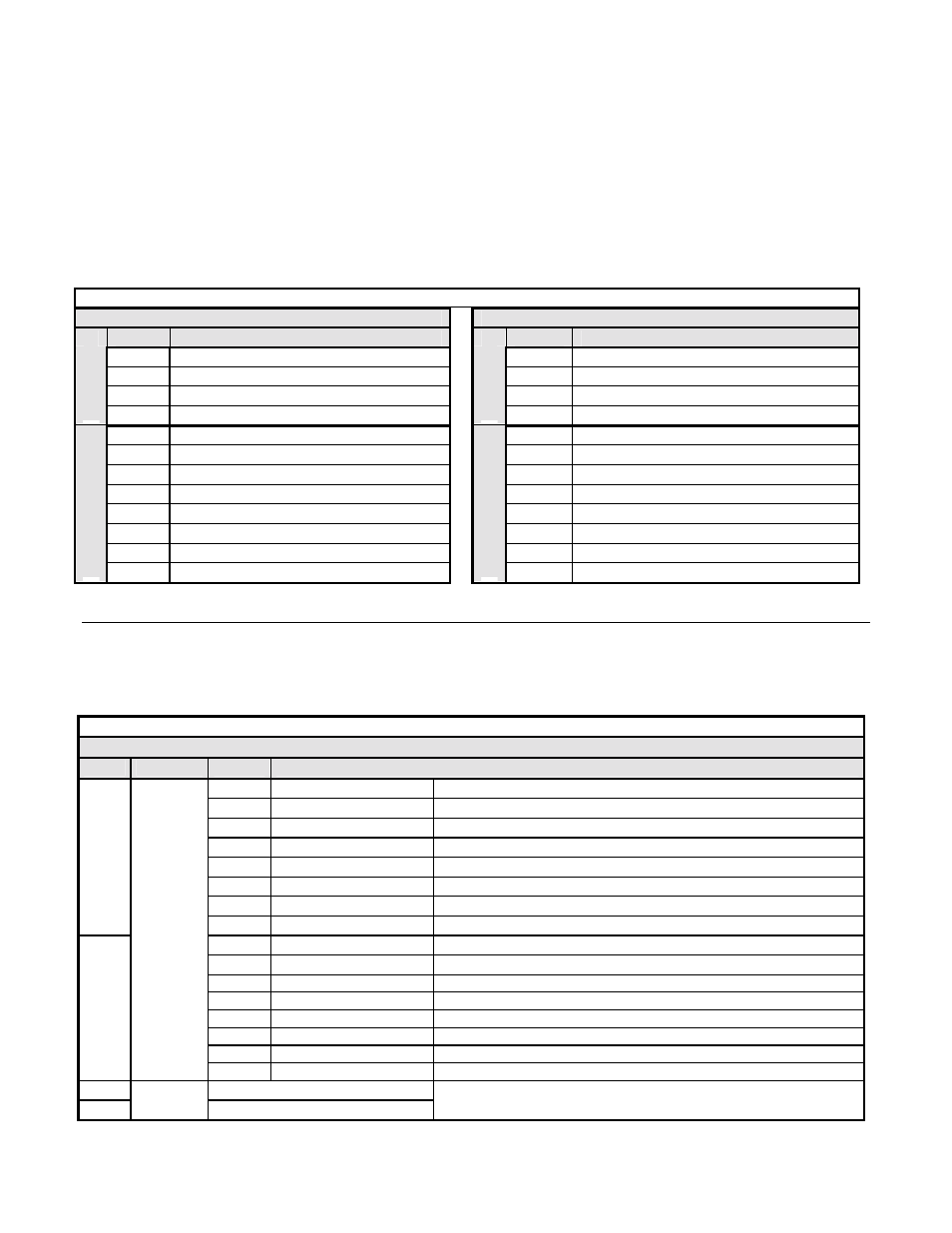
Table 3.7 – PROFIBUS-DP 6 Word Input/Output Message I/O Table
Output Data (PROFIBUS-DP Master -> Drive)
Input Data (Drive -> PROFIBUS-DP Master )
Byte
Function
Byte
Function
0
RUN Operation Command MSB
0
Drive Status MSB
1
RUN Operation Command LSB
1
Drive Status LSB
2
Frequency Reference MSB
2
Frequency Feedback MSB
Fast I/O
3
Frequency Reference LSB
Fast I/O
3
Frequency Feedback LSB
4
Function Code
4
Function Code
5
Starting Address MSB
5
Starting Address MSB
6
Starting Address LSB
6
Starting Address LSB
7
Data Length (always 2)
7
Data Length (always 2)
8
Data 1 MSB
8
Data 1 MSB
9
Data 1 LSB
9
Data 1 LSB
10 Reserved
10 Reserved
Parameter Access
11 Handshake
Register
Parameter Access
11 Handshake
Register
#
Fast I/O Output Data
The fast I/O output data area is used to transfer parameter data directly to the drive via a dual port RAM interface. The following table
details the functions of the fast I/O output data (Bytes 0 to 3) For detailed explanation of the terminal and multi-function inputs and outputs,
refer to the appropriate drive technical manual.
Table 3.8 – 6 Word Input/Output Message Fast I/O Output Data
Fast I/O Output Data (PROFIBUS-DP Master -> Drive)
Byte
Function
Bit
Note
0h
Fwd Run/Stop
1 = RUN Forward (Enabled when b1-02 is set to 3)
1h
Rev Run/Stop
1 = RUN Reverse (Enabled when b1-02 is set to 3)
2h
Multi-Function Input 3
1 = Close
3h
Multi-Function Input 4
1 = Close
4h
Multi-Function Input 5
1 = Close
5h
Multi-Function Input 6
1 = Close
6h
Multi-Function Input 7
1 = Close
0
7h
Multi-Function Input 8
1 = Close (F7U and G7 drives only)
8h
External Fault
1 = External Error
9h
Fault Reset
1 = Reset Fault
Ah
Multi-Function Input 9
1 = Close (G7 drive only)
Bh
Multi-Function Input 10
1 = Close (G7 drive only)
Ch
Multi-Function Input 11
1 = Close (G7 drive only)
Dh
Multi-Function Input 12
1 = Close (G7 drive only)
Eh
Clear Error Log
1
Command
Reference
Fh
External Base Block
2
Frequency Reference MSB
3
Frequency
Reference
Frequency Reference LS
1 = 0.01Hz
scaling is dependent on the setting of parameter o1-03