Parameter access command message structure, Parameter access response message structure, Network communications 3-6 – Yaskawa Profibus-DP Option Card CM061 User Manual
Page 30
Network Communications 3-6
#
Parameter Access Command Message Structure
Two command, output, functions are available, read parameter data, 03h, and write parameter data, 10h. If no parameter access
communications is desired, use 00h as the function code. These function codes are programmed in byte 16 of the 16 word input/output
message. Bytes 17 and 18 contain the parameter access address of the parameter to be accessed. Byte 19 contains the number of data bytes
to be read from or written to the drive. Since each parameter consists of two bytes, this value is incremented by two for each parameter
accessed. Bytes 19 through 27 contain the data to be written to the selected parameter. If the command is to read parameter data, bytes 19
through 27 must be set to 0.
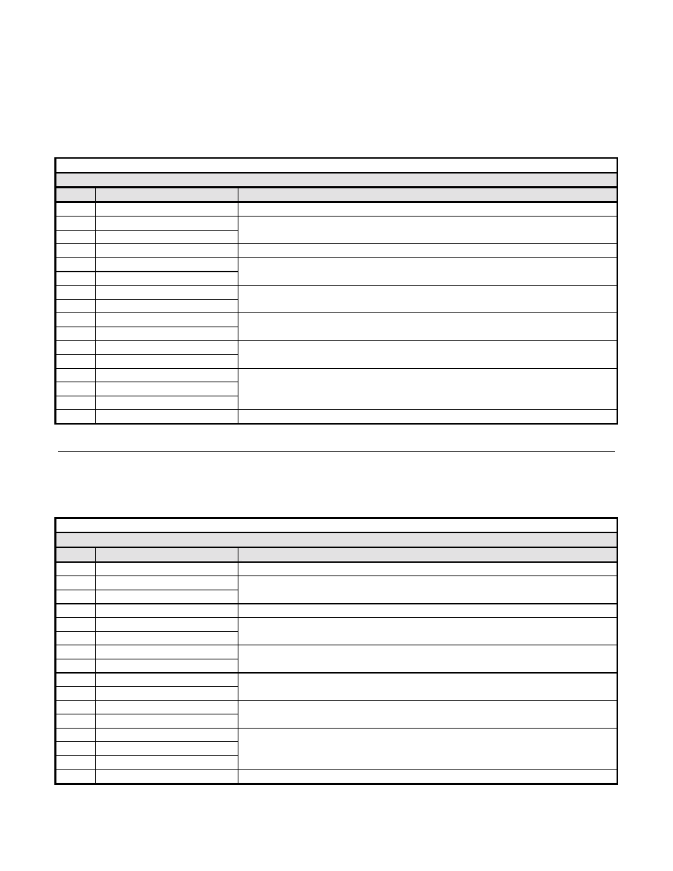
Table 3.4 – 16 Word Input/Output Message Parameter Access Command Structure
Output Data – Parameter Access Command Message (PROFIBUS-DP Master -> Drive)
Byte
Name
Function
16 Function
Code
Parameter Access Command Code (Read data = 03h, Write data = 10h)
17 Starting
Address
MSB
18 Starting
Address
LSB
The first register to be read or written
19
Data Quantity
Bytes of data (2 x Number of parameters to be read or written)
20
Data 1 MSB
21
Data 1 LSB
Value of data to write to the drive parameter Starting Address
22
Data 2 MSB
23
Data 2 LSB
Value of data to write to the drive parameter Starting Address + 1
24
Data 3 MSB
25
Data 3 LSB
Value of data to write to the drive parameter Starting Address + 2
26
Data 4 MSB
27
Data 4 LSB
Value of data to write to the drive parameter Starting Address + 3
28 Reserved
29 Reserved
30 Reserved
31
Handshaking Register
Synchronizes drive communication with PROFIBUS-DP Master
#
Parameter Access Response Message Structure
The standard Parameter Access response structure is described below. In a non-erroneous response, the Function Code, Starting Register
and Data Quantity are identical to the command message. If the command function code is 03h, read data, the data bytes will contain the
values of the requested parameters. If the command function code is 10h, write data, the data bytes will contain 0 and should be ignored.
Table 3.5 – 16 Word Input/Output Message Parameter Access Response Structure
Input Data – Parameter Access Response Message (Drive -> PROFIBUS-DP Master )
Byte
Name
Function
16 Function
Code
Parameter Access Response Code (Command code or command code & 80h for error)
17 Starting
Address
MSB
18 Starting
Address
LSB
The first register to be read or written
19
Data Quantity
Bytes of data (2 x Number of parameters to be read or written)
20
Data 1 MSB
21
Data 1 LSB
Value of data read from the drive parameter Starting Address
22
Data 2 MSB
23
Data 2 LSB
Value of data read from the drive parameter Starting Address + 1
24
Data 3 MSB
25
Data 3 LSB
Value of data read from the drive parameter Starting Address + 2
26
Data 4 MSB
27
Data 4 LSB
Value of data read from the drive parameter Starting Address + 3
28 Reserved
29 Reserved
30 Reserved
31
Handshaking Register
Synchronizes drive communication with PROFIBUS-DP Master