Installation 1-7 – Yaskawa Profibus-DP Option Card CM061 User Manual
Page 13
Installation 1-7
Connect The Drive To The PROFIBUS-DP Communications Network.
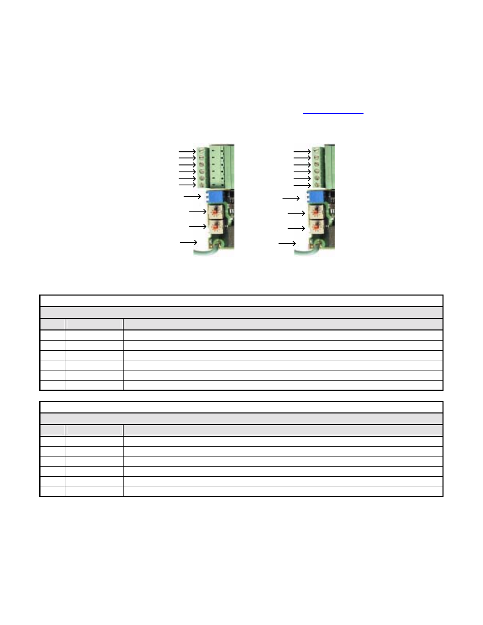
! Determine the type of connector on the PROFIBUS-DP Option. Connector Style A is a modified Phoenix pluggable connector.
The modification can be seen on the back of the connector as a small circuit board. Connector Style B is a standard Phoenix
pluggable connector without modification.
! Connect the PROFIBUS-DP network cable to the PROFIBUS-DP Option. Refer to the appropriate connection drawing in Figure
1.3 below for your connector style.
! Use standard PROFIBUS-DP cable as specified by the PROFIBUS Organization
www.profibus.org
.
Refer to Appendix D
Troubleshooting for more information on network cabling.
! Tie the PROFIBUS-DP cable to a point near the connector to provide strain relief for the connector and cable connection.
Figure 1.3 – PROFIBUS-DP Option Connections
Table 1.2 – PROFIBUS-DP Cable Connections – Style A
Connector Style A
Pin
Name
Function
1
A In-(Green)
Negative Input RxD/TxD (Connected to the previous device)
2
B-In (Red)
Positive Input RxD/TxD (Connected to the previous device)
3
A Out-(Green)
Negative Output RxD/TxD (Connected to the next device)
4
B-Out (Red)
Positive Output RxD/TxD (Connected to the next device)
5
Shield
BUS cable shield (Connected to PE internally on the communication option)
6 Reserved
Table 1.3 – PROFIBUS-DP Cable Connections – Style B
Connector Style B
Pin
Name
Function
1 Reserved
2 Reserved
3
A In/ Out-(Green)
Negative Input/Output RxD/TxD (Connected to the previous device)
4
B-In/Out (Red)
Positive Input/Output RxD/TxD (Connected to the next device)
5
Shield
BUS cable shield (Connected to PE internally on the communication option)
6 Reserved
C
o
n
n
e
c
to
r
S
ty
le
A
Reserved
Shield
1
B Out (Red)
4
5
6
Ground
A In (Green)
2
B In (Red)
A Out (Green)
3
C
o
n
n
e
c
to
r
S
ty
le
B
Reserved
Shield
1
2
A In/Out (Green)
3
B In/Out (Red)
4
5
6
Reserved
Reserved
Ground
Termination
S2
S1
Termination
S2
S1