Fast i/o input data, Parameter access area, Network communications 3-5 – Yaskawa Profibus-DP Option Card CM061 User Manual
Page 29
Network Communications 3-5
#
Fast I/O Input Data
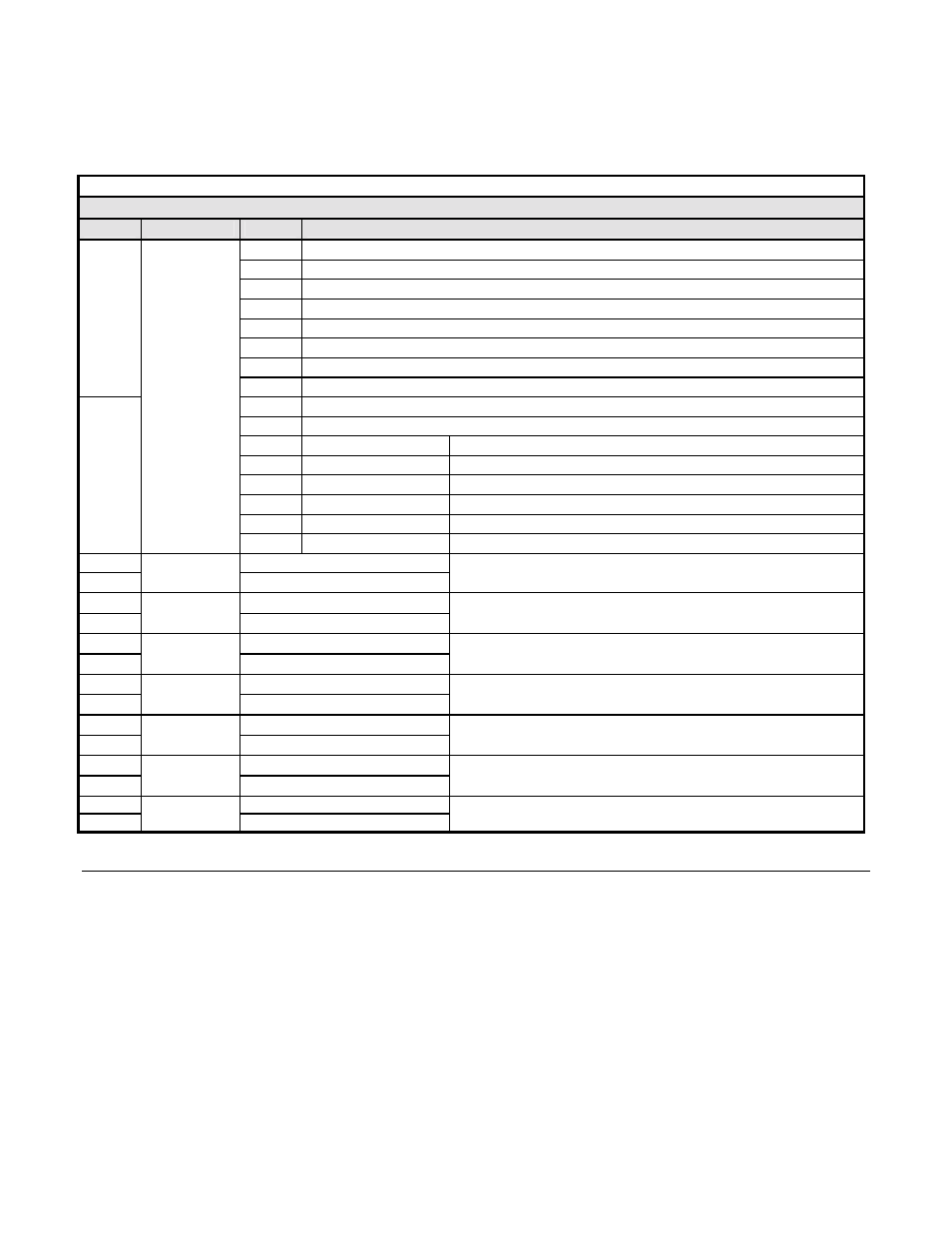
The fast I/O input data area is used to transfer parameter data directly from the drive via a dual port RAM interface. The following table
details the functions of the fast I/O input data (Bytes 0 to 15). For detailed explanation of the terminal and multi-function inputs and
outputs, refer to the appropriate drive technical manual.
Table 3.3 – 16 Word Input/Output Message Fast I/O Input Data
Fast I/O Input Data (Drive -> PROFIBUS-DP Master )
Byte
Function
Bit
Note
0h @
RUN
1h
@ Zero Speed
2h @
Reverse
3h
@ Reset Signal
4h @
Frequency
Agree
5h
@ Drive Ready (Rdy)
6h
@ Minor Fault (Alarm)
0
7h
@ Major Fault
8h
@ OPE Error
9h
@ Fault Restart
Ah
Local/Remote
1 = Remote Operation
Bh
Multi-Function Output 1
1 = Close
Ch
Multi-Function Output 2
1 = Close
Dh
Multi-Function Output 3
1 = Close
Eh
Motor Select
1 = #2 Motor
1
Drive
Status
Fh
@ Zero Servo Complete
2
Frequency Reference MSB
3
Frequency
Reference
Frequency Reference LSB
0.1Hz
scaling is dependent on the setting of parameter o1-03
4
Torque Reference MSB
5
Torque
Reference
Torque Reference LSB
Flux Vector mode
6
Speed Detection PG Count MSB
7
Speed Detection
PG Count
Speed Detection PG Count LSB
PG Option must be installed
8
Frequency Reference MSB
9
Frequency
Reference
Frequency Reference LSB
0.1Hz
scaling is dependent on the setting of parameter o1-03
10
Output Frequency MSB
11
Output
Frequency
Output Frequency LSB
0.1Hz
scaling is dependent on the setting of parameter o1-03
12
Output Current MSB
13
Output
Current
Output Current LSB
Scaled Value
Output current(Drive rating/8192)
14
Analog Input @ Terminal 14 MSB
15
AI
Analog Input @ Terminal 14 LSB
±10vdc = ±100%
#
Parameter Access Area
This area is used to read and write parameter data from and to the drive. The PROFIBUS-DP Master completes the Parameter Access
command (output) message and waits for and then processes the data returned in the Parameter Access response (input) message. These
messages may contain 1 - 4 words of data. The handshaking byte is used to synchronize the communications between the PROFIBUS-DP
Master and the drive. This is necessary due to the additional time required for the drive to process the message. Refer to the Handshaking
section of this chapter for more information on handshaking. Note: Care must be taken when writing certain parameters to the drive as
other parameters may be dependant on them. Control method, A1-02, maximum Frequency, E1-04, and Acc/Dec Scale Time, C1-10, are
just a few. Refer to the appropriate drive MODBUS
technical manual for more information.