3 word i/os message, Fast i/o output data, Network communications 3-10 – Yaskawa Profibus-DP Option Card CM061 User Manual
Page 34
Network Communications 3-10
3 Word I/Os Message
The 3 word I/Os, combined input/output, messages have only one fixed area. This is the most frequently used data and is referred to as the
fast I/O data. 3 Word messages are used when processor memory is a critical factor in the network design. As shown below, the 3 word I/Os
message contains only the minimum drive data.
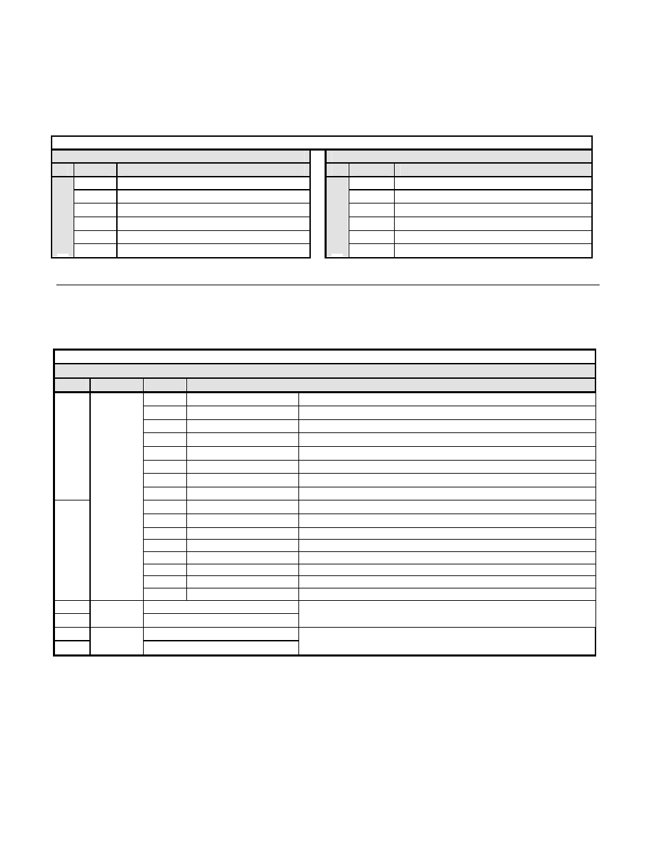
Table 3.12 – PROFIBUS-DP 3 Word Message I/O Table
OUTPUT DATA PROFIBUS-DP Master -> Drive
Drive INPUT DATA -> PROFIBUS-DP Master
Byte
Function
Byte
Function
0
RUN Operation Command MSB
0
Drive Status MSB
1
RUN Operation Command LSB
1
Drive Status LSB
2
Frequency Reference MSB
2
Frequency Feedback MSB
3
Frequency Reference LSB
3
Frequency Feedback LSB
4
Torque Reference MSB
4
Output Current MSB
Fast I/O
5
Torque Reference LSB
Fast I/O
5
Output Current LSB
#
Fast I/O Output Data
The fast I/O output data area is used to transfer parameter data directly to the drive via a dual port RAM interface. The following table
details the functions of the fast I/O output data (Bytes 0 to 5) For detailed explanation of the terminal and multi-function inputs and outputs,
refer to the appropriate drive technical manual.
Table 3.13 – 3 Word Input/Output Message Fast I/O Output Data
Fast I/O Output Data (PROFIBUS-DP Master -> Drive)
Byte
Function
Bit
Note
0h
Fwd Run/Stop
1 = RUN Forward (Enabled when b1-02 is set to 3)
1h
Rev Run/Stop
1 = RUN Reverse (Enabled when b1-02 is set to 3)
2h
Multi-Function Input 3
1 = Close
3h
Multi-Function Input 4
1 = Close
4h
Multi-Function Input 5
1 = Close
5h
Multi-Function Input 6
1 = Close
6h
Multi-Function Input 7
1 = Close
0
7h
Multi-Function Input 8
1 = Close (F7U and G7 drives only)
8h
External Fault
1 = External Error
9h
Fault Reset
1 = Reset Fault
Ah
Multi-Function Input 9
1 = Close (G7 drive only)
Bh
Multi-Function Input 10
1 = Close (G7 drive only)
Ch
Multi-Function Input 11
1 = Close (G7 drive only)
Dh
Multi-Function Input 12
1 = Close (G7 drive only)
Eh
Clear Error Log
1
Command
Reference
Fh
External Base Block
2
Frequency Reference MSB
3
Frequency
Reference
Frequency Reference LS
1 = 0.01Hz
scaling is dependent on the setting of parameter o1-03
4
Torque Reference MSB
5
Torque
Reference
Torque Reference LSB
Flux Vector Mode