7 external terminals, Main circuit terminal functions, Control circuit terminal functions – Yaskawa Varispeed-656 DC5 User Manual
Page 38
E-28
3.7
EXTERNAL TERMINALS
Main Circuit Terminal Functions
Control Circuit Terminal Functions
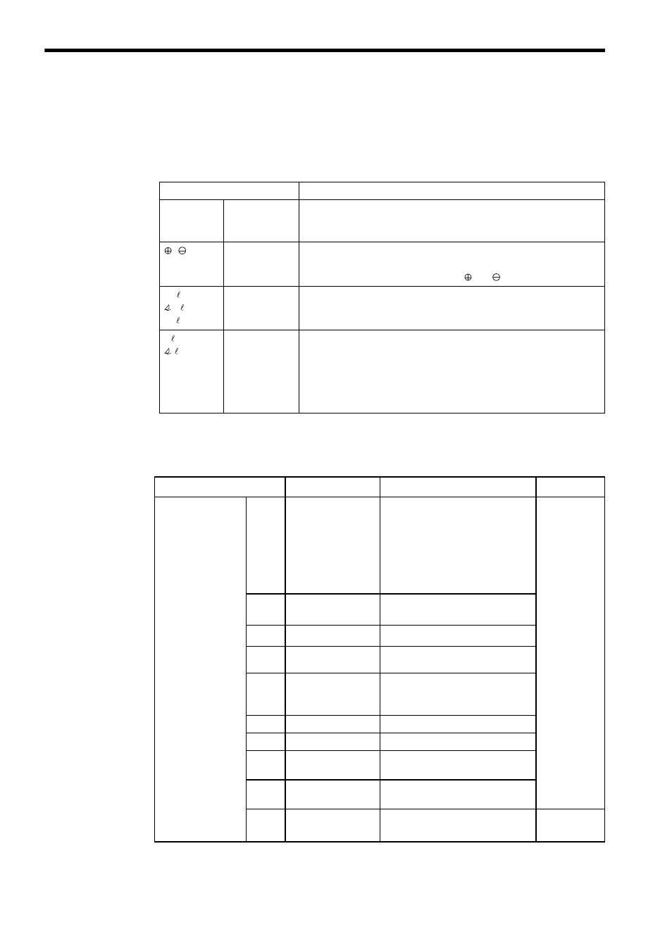
Table 6 Main Circuit Terminal Functions
Terminal Symbol
Description
R/L1
S/L2
T/L3
VS-656DC5
Main Circuit
Input
Main circuit AC power supply input terminal for the VS-656DC5
,
VS-656DC5
Main Circuit
Output
Main circuit DC output terminal for the VS-656DC5
• Connects to the Inverter’s DC power supply voltage input terminals.
Two terminals are provided for both and .
r1/ 11
1/ 21
t1/ 31
Power Supply
Voltage
Detection
Detects the phase sequence and the voltage level.
• Connect to the power side of the input reactor.
r/ 1
/ 2
Power Input
for FAN and
MC
Supplies power for the cooling fan and inrush current prevention MC of
the VS-656DC5.
• Terminals may not be provided for some VS-656DC5s depending on
their capacities.
• The power supply voltage jumper in the VS-656DC5 must be set
depending on the voltage value to be supplied.
Table 7 Control Circuit Terminal Functions
Terminal Name
*1
Signal Name
Function
Signal Level
Sequence Input
1
RUN-SB
VS-656DC5 starts operation at
“Closed.” One-shot trigger inputs
are available: Once the data is input,
the VS-656DC5 keeps running even
at “Open.”
To start the VS-656DC5 operation,
set terminal 2 to “Closed.”
*2
24 VDC 8 mA
Photocoupler
isolation
2
STOP
VS-656DC5 stops at “Open.”
3
External Fault
−
4
Fault Reset
*2
5 - 7
Multi-function
Contact Input
Terminal
Set to “Unused” prior to shipment.
Constants H1-03 to H1-06 can be
used for the setting.
8
External Baseblock
Baseblock at “Closed.”
11
Sequence Common
−
35
Photocoupler Internal
Common
−
36
+24-V Power Sup-
ply for Sequence
−
12
Shielded Sheath Wire −
−