Yaskawa P7 to P1000 User Manual
Page 39
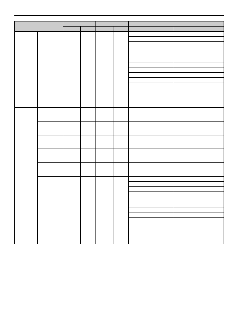
13 Appendix 2 Parameter Cross Reference
YASKAWA PL.P1000.01 P7 to P1000 - Product Transition Guide
39
Multi-Function
Analog Output
Analog Output 1
Terminal FM
Monitor
Selection
H4-01
2
H4-01
102
53: PI Feedback 2
505: PI Feedback 2
—
506: PI Differential Feedback
—
514: PI Output 2 (U4)
—
515: PI Output 2 (L4)
—
517: PI2 Set-point
—
518: PI2 Feedback
—
519: PI Input 2
—
520: Output
—
599:PID Setpoint Command
—
618: PG1 Couter Value
—
619: PG2 Counter Value
—
620: UP/DOWN 2 Bias
—
621: Offset Frequency
Note: 100% = 10 Vdc output
FM gain setting (H4-02).
—
Multi-Function
Analog Output
Analog Output 1
Terminal FM
Gain
H4-02
100%
H4-02
100.0%
—
Analog Output 1
Terminal FM
Bias
H4-03
0.0%
H4-03
0.0%
—
Analog Output 2
Terminal AM
Selection
H4-04
8*
H4-04
103*
*Refer to parameter H4-01 for details.
Analog Output 2
Terminal AM
Gain
H4-05
50.0%
H4-05
50.0%
—
Analog Output 2
Terminal AM
Bias
H4-06
0.0%
H4-06
0.0%
—
Analog Output 1
Signal Level
(FM) Selection
H4-07
0
H4-07
0
H4-07
H4-07
0: 0 to +10 V output
0: 0 to +10 Vdc output
—
1: -10 to 10 Vdc output
2: 4 to 20 mA*
2: 4 to 20 mA
Analog Output 2
Signal Level
(AM) Selection
H4-08
0
H4-08
0
H4-08
H4-08
0: 0 to +10 V output
0: 0 to +10 Vdc output
—
1: -10 to 10 Vdc output
2: 4 to 20 mA*
2: 4 to 20 mA
* An analog output of 4-20mA
cannot be used with the
standard terminal board. A
terminal board with a shunt
connector CN15 is needed,
part ETC.
Parameter Name
P7
P1000
Setting
Parameter
Default
Parameter
Default
P7
P1000