Yaskawa P7 to P1000 User Manual
Page 32
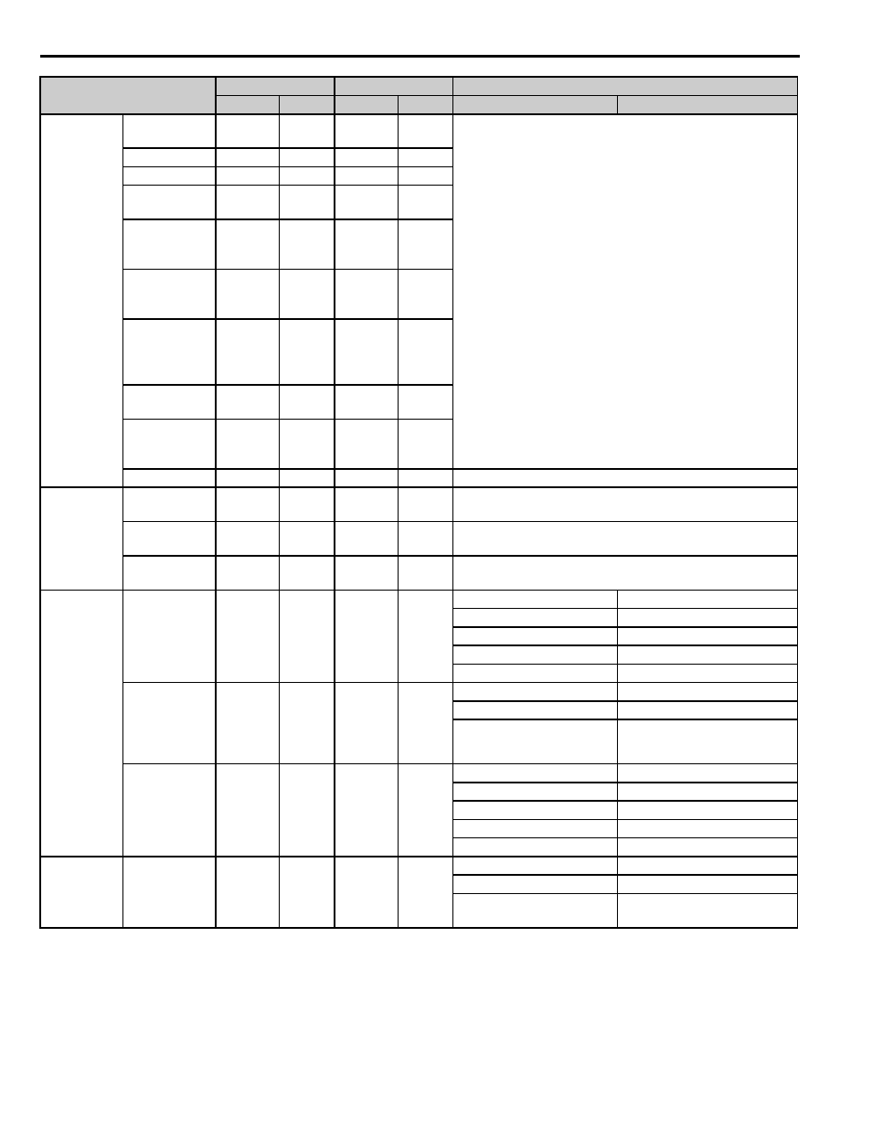
13 Appendix 2 Parameter Cross Reference
32
YASKAWA PL.P1000.01 P7 to P1000 - Product Transition Guide
V/f
Characteristics
Max Output
Frequency
E1-04
60.0 Hz
E1-04
60.0 Hz *
*Depends on parameters A1-02 Control Method Selection (P7
only), o2-04, Drive Model Selection, and E5-01, Motor Code
Selection.
Max Voltage
E1-05
240.0 V*
E1-05
230.0 V*
Base Frequency
E1-06
60.0 Hz *
E1-06
60.0 Hz*
Mid. Output
Frequency
E1-07
3.0 Hz *
E1-07
3.0 Hz*
Mid. Output
Frequency
Voltage
E1-08
18.0 V*
E1-08
17.3 V*
Minimum
Output
Frequency
E1-09
1.5 Hz *
E1-09
1.5 Hz*
Minimum
Output
Frequency
Voltage
E1-10
10.5 V*
E1-10
10.2 V*
Mid. Output
Frequency 2
E1-11
0.0 Hz
E1-11
0.0 Hz
Mid. Output
Frequency
Voltage 2
E1-12
0.0 V
E1-12
0.0 V
Base Voltage
E1-13
0.0 V
E1-13
0.0 V
—
Motor
Parameters
Motor Rated
Current
E2-01
*
E2-01
*
*For P1000, dependent on drive capacity parameter o2-04
Motor No-Load
Current
E2-03
*
E2-03
*
*For P1000, dependent on drive capacity parameter o2-04
Motor Line-to-
Line Resistance
E2-05
*
E2-05
*
*For P1000, dependent on drive capacity parameter o2-04
Comm. Option
Card
Operation
Selection After
Communications
Error
F6-01
1
F6-01
1
F6-01
F6-01
0: Ramp to stop
0: Ramp to stop
1: Coast to stop
1: Coast to stop
2: Fast Stop
2: Fast Stop
3: Alarm Only
3: Alarm Only
External Fault
from Comm.
Option Board
Detection
Selection
F6-02
0
F6-02
0
F6-02
F6-02
0: Always detected
0: Always detected
1: Detected during run
1: Detected during run
External Fault
from Comm.
Option Board
Operation
Selection
F6-03
1
F6-03
1
F6-03
F6-03
0: Ramp to stop
0: Ramp to stop
1: Coast to stop
1: Coast to stop
2: Fast Stop
2: Fast Stop
3: Alarm Only
3: Alarm Only
Comm. Option
Card
Current Unit
Monitor Display
F6-05
0
—
—
F6-05
—
0: A Display (Amps)
—
1: 100%/8192
(Drive Rated Current)
—
Parameter Name
P7
P1000
Setting
Parameter
Default
Parameter
Default
P7
P1000