8 team power cabling – SMA SC 100LV-560HE User Manual
Page 64
Electrical Connection
SMA Solar Technology AG
64
SC125_560HE-IEN083220
Installation Guide
5.2.8 Team Power Cabling
In chapter 5.1.9 „Team cabling (optional)“ (44), the internal power cabling in the inverter is
described for the team concept. To connect the inverters which are part of the team, the external team
power cabling of the inverter has now to be carried out one under the other.
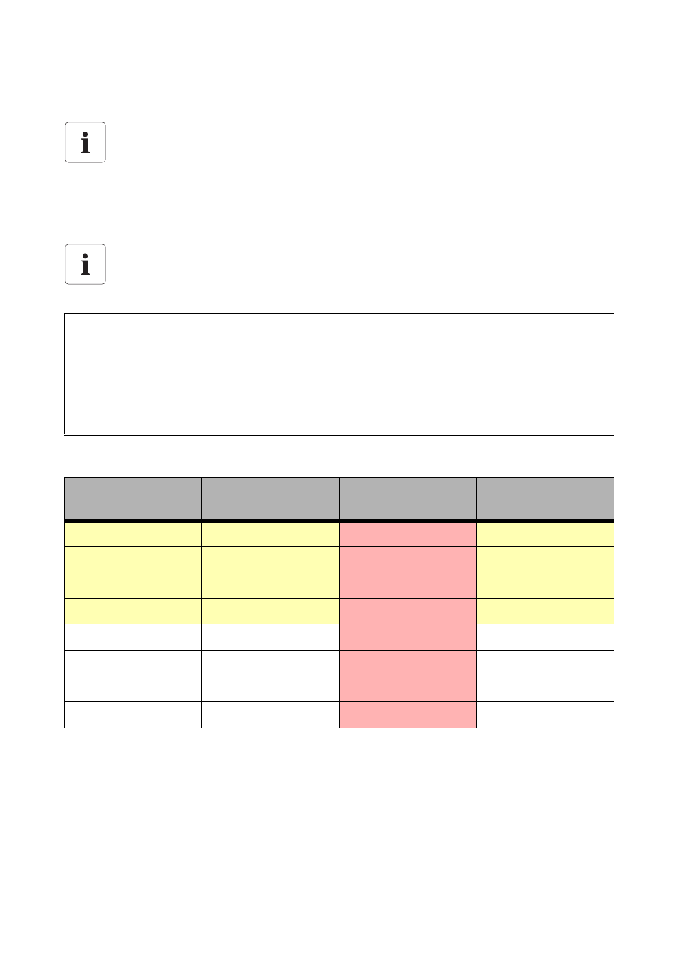
The following table contains the corresponding information about DC team current.
The required cables (Standard: 5m) for connecting the team cabling are included in the
delivery.
Realization of team cabling
When connecting the team configuration, it is obligatory to follow the circuit diagram
included in the delivery.
ATTENTION!
Possible damage to the cabling!
The power cables of the team connection of the inverters must have a DC voltage
resistance of a minimum of 1000 V DC and must be dimensioned for the maximum
expected DC team current (at 100% nominal power).
Sunny Central
max. DC current [A]
input
max. team current
[A]
connection terminal
WFF [mm²]
Sunny Central 100LV
430
224
185
Sunny Central 125LV
448
224
185
Sunny Central 150
354
177
185
Sunny Central 200
472
236
185
Sunny Central 250
591
296
185
Sunny Central 350
800
400
300
Sunny Central 500
2 x 591 (1182)
2 x 296
2 x 300
Sunny Central 560
2 x 591 (1182)
2 x 296
2 x 300