H1-02 – SMA SC 100LV-560HE User Manual
Page 62
Electrical Connection
SMA Solar Technology AG
62
SC125_560HE-IEN083220
Installation Guide
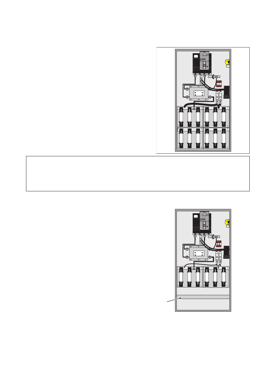
DC cabling Sunny Central 350 / Sunny Central 350HE
The DC input fuses in the inverter are usually arranged in
one row. The DC fuses in the switch cabinets of the type
Sunny Central 350 / Sunny Central 350HE are attached
one behind the other and at different heights on two
mounting plates. The special connection version of the
DC fuses in the Sunny Central 350 / Sunny
Central 350HE can be seen in the figure on the right.
Installation of the DC cabling:
1. For the installation of the DC cabling, the rear DC
fuses must be installed first. Firstly, the front
mounting plate with the DC protection unit on top
must be completely dismantled. Now you can also
see the concealed cable clamp rail (A).
Right figure: View of the rear DC fuses on the
mounting plate
2. Installation of DC cabling.
3. Install front mounting plate.
4. Install the remaining DC cabling.
The inputs fused on the positive and negative sides are
designed as NH fuses (except Sunny Central 500HE and
Sunny Central 560HE) and are connected on the DC
rails L+ and L-.
ATTENTION!
Possible damage to the cabling!
The rear cable clamp rail is installed behind the DC fuse unit located in the front.
H1-02
L-
L+
L-
L+
L+
L-
L-
L-
L+
L-
L+
L-
H1-02
L-
L+
L-
L+
L+
L-
L-
L-
L+
L-
L+
L-
A