SMA SPEEDWIRE V.1.6 User Manual
Page 19
SMA Solar Technology AG
5 Connection
Installation Manual
SWWEBCONDM-IA-en-16
19
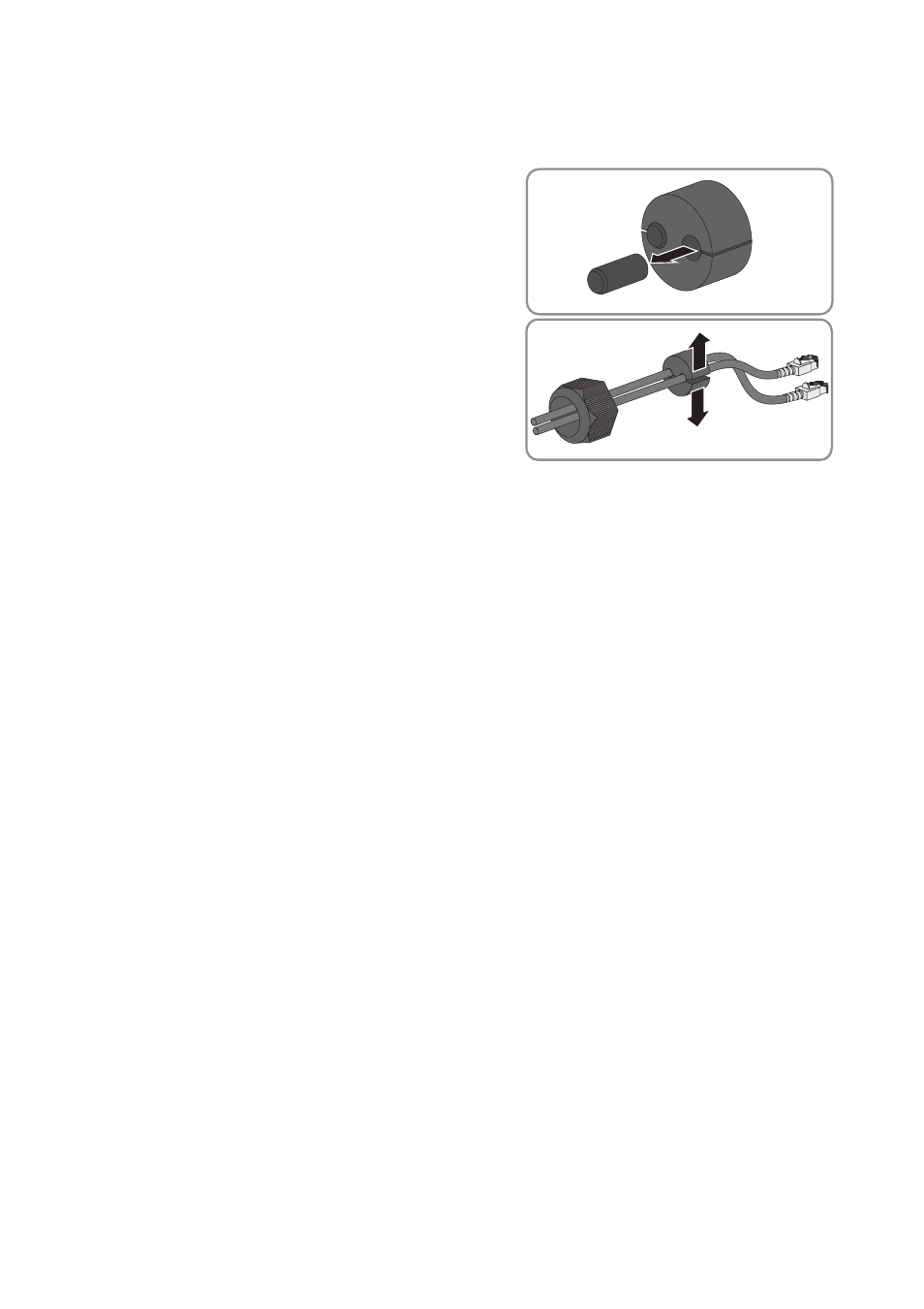
5. Lead the network cables from the outside into the inverter through the loose swivel nut and the
cable gland.
6. For each network cable, remove one of the filler
plugs from the seal and retain for later
decommissioning.
7. Lead the network cables through the swivel nut and
into the seal. Route the network cable plugs into the
inverter to the network ports.
8. Press the seal into the cable gland. Ensure that any unused cable openings are sealed with filler
plugs.
9. Screw the swivel nut of the cable gland on loosely.
10. Insert the network cables into the network ports. This can be done in any order.
11. Fasten the swivel nut on the cable gland hand-tight. This will fix the network cables in place.
12. Flip the display down and fasten the screw of the display hand-tight.
13. Close the inverter (see inverter installation manual).
14. In a small-scale PV system, depending on the system topology, connect at least one inverter
directly to the router using a network cable.
15. In a large-scale PV power plant with Cluster Controller, connect the Cluster Controller to the
Speedwire network in accordance with the required network topology (see installation manual
of the Cluster Controller).