5 connection, 1 mounting position and cable route – SMA SPEEDWIRE V.1.6 User Manual
Page 15
SMA Solar Technology AG
5 Connection
Installation Manual
SWWEBCONDM-IA-en-16
15
5 Connection
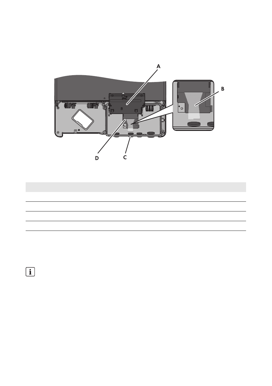
5.1 Mounting Position and Cable Route
Figure 5: Mounting position and cable route in the inverter with the lower enclosure lid open and the display
flipped up
5.2 Cable Requirements and Information on Cable Routing
The cable length and cable quality affect the signal strength in the Speedwire network. Observe the
following cable requirements and the information on cable laying.
Position
Designation
A
Flipped up display
B
Cable route to the network ports
C
Opening in the inverter enclosure with filler plug
D
Mounting position of the Speedwire/Webconnect data module in the inverter
Interference in data transmission due to unshielded energy cables
If unshielded power cables are used, they generate an electromagnetic field during operation
which may induce interference in network cables during data transmission.
• When laying network cables, observe the following minimum clearances to unshielded
energy cables:
– For installation without separating strip: at least 200 mm
– For installation with aluminum separating strip: at least 100 mm
– For installation with steel separating strip: at least 50 mm