Notice, 1 network topology – SMA FLX Series User Manual
Page 49
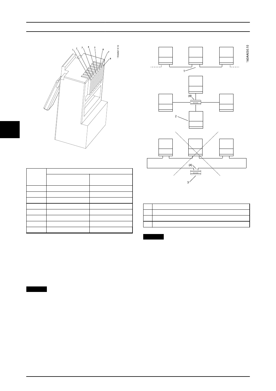
Illustration 5.15 RJ-45 Pinout Detail for Ethernet
Pinout
Ethernet
Colour Standard
Cat 5
T-568A
Cat 5
T-568B
1. RX+
Green/white
Orange/white
2. RX
Green
Orange
3. TX+
Orange/white
Green/white
4.
Blue
Blue
5.
Blue/white
Blue/white
6. TX-
Orange
Green
7.
Brown/white
Brown/white
8.
Brown
Brown
5.9.1 Network Topology
The inverter has 2 Ethernet RJ-45 connectors enabling the
connection of several inverters in a line topology as an
alternative to the typical star topology. The 2 ports are
similar and may be used interchangeably. For RS-485, only
linear daisy chain connections can be used.
NOTICE
Ring topology is not permitted.
Illustration 5.16 Network Topology
1
Linear Daisy Chain
2
Star Topology
3
Ring Topology (not permitted)
(4)
(Ethernet Switch)
NOTICE
The 2 network types cannot be mixed. The inverters can
only be connected in networks which are either solely
RS-485 or solely Ethernet.
Technical Data
48
L00410568-03_2q / Rev. date: 2014-06-20
5
5
- SUNNY PORTAL (75 pages)
- SB 2.5-1VL-40 (60 pages)
- SB 2.5-1VL-40 Service Manual (36 pages)
- SB 240 (78 pages)
- FLX Pro 17 (12 pages)
- FLX Series GSM Option Kit (48 pages)
- FLX Series Sensor Interface Option (51 pages)
- FLX Series PLA Option (62 pages)
- 25000TL (52 pages)
- 25000TL Installation (40 pages)
- 25000TL Service Manual (46 pages)
- CBL-DC-CMB8-10 (24 pages)
- 25000TL Quick Installation Guide (36 pages)
- STP 60-10 Replacing a Defective Fan (12 pages)
- STP 60-10 Replacing Defective Surge Arresters (12 pages)
- Webconnect Systems in SUNNY PORTAL (69 pages)
- STP 12000TL (68 pages)
- STP 60-US-10 Installation (232 pages)
- 485 Data Module Type B (24 pages)
- STP 12000TL Quick Installation Guide (28 pages)
- 1000-US (52 pages)
- STP 24000TL-US (78 pages)
- STP 17000TL (60 pages)
- STP 20000TL (2 pages)
- SB 6000TL Service Manual (46 pages)
- MULTIFUNCTION RELAY (32 pages)
- SB 5000TL (60 pages)
- SB 5000TL Quick Installation Guide (32 pages)
- FANKIT01-10 (24 pages)
- SB 7700TL-US (28 pages)
- FANKIT02-10 (24 pages)
- SB 7700TL-US Installation (96 pages)
- SUNNY MINI CENTRAL (48 pages)
- DC Disconnect Switch For SB 3800-U (32 pages)
- SB 4000-US (100 pages)
- DB-DC-DISCON (4 pages)
- SB 3800-U (86 pages)
- POWER BALANCER (28 pages)
- SB 8000-US (104 pages)
- SB 11000TL‑US (40 pages)
- SMC 11000TL (24 pages)
- SBCBTL6 (36 pages)
- SB 11000TL‑US Installation (92 pages)
- SMC 11000TL Installation (96 pages)