Defining contours, Fundamentals – HEIDENHAIN iTNC 530 (340 49x-05) Pilot User Manual
Page 168
168
Definin
g Contours
Defining Contours
Fundamentals
Contours are defined in separate files (file type .HC). Since .HC files
contain pure descriptions of contours—only geometry data, no
technology data—they can be used flexibly: as contour trains, as pockets
or as islands.
You can create HC files either with the path functions or by using the DXF
converter (software option) to import it from existing DXF files.
Existing contour descriptions in older plain-language programs (.H files)
can easily be converted into smarT.NC contour descriptions (see
Page 177).
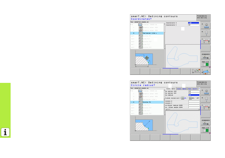
Just as with unit programs and the pattern generator, smarT.NC displays
each contour element in the tree view (
1
) with an appropriate icon. Enter
the data for each contour element in the form (
2
). In the FK free contour
programming, along with the overview form (
3
) there are up to three
additional detail forms (
4
) in which you can enter data (see figure at
bottom right).
1
1
1
2
1
3
1
4