Please note while programming, Cycle parameters – HEIDENHAIN iTNC 530 (340 49x-05) Cycle programming User Manual
Page 349
HEIDENHAIN iTNC 530
349
15.6 D
A
TUM FR
OM INSIDE OF CIR
C
LE (Cy
c
le 412, DIN/ISO: G412)
Please note while programming:
Cycle parameters
U
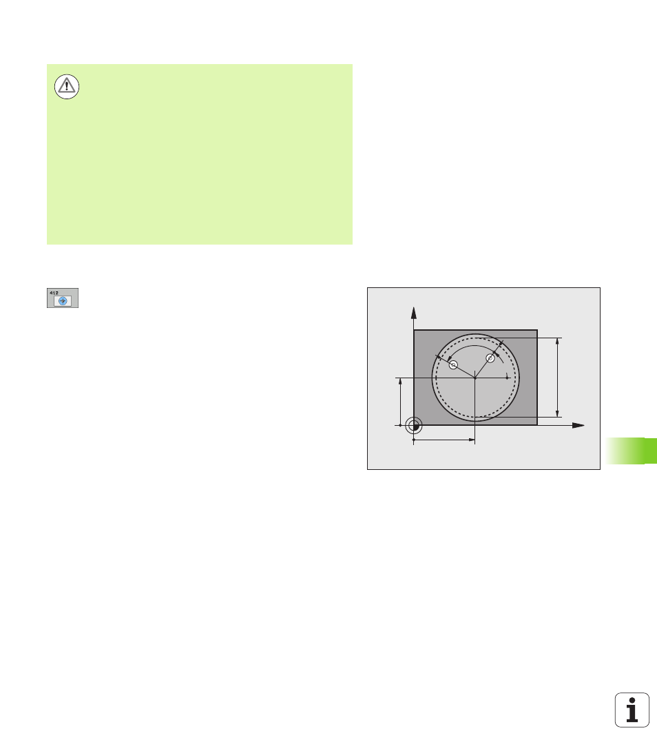
Center in 1st axis
Q321 (absolute): Center of the
pocket in the reference axis of the working plane.
Input range: -99999.9999 to 99999.9999
U
Center in 2nd axis
Q322 (absolute): Center of the
pocket in the minor axis of the working plane. If you
program Q322 = 0, the TNC aligns the hole center to
the positive Y axis. If you program Q322 not equal to
0, then the TNC aligns the hole center to the nominal
position. Input range: -99999.9999 to 99999.9999
U
Nominal diameter
Q262: Approximate diameter of the
circular pocket (or hole). Enter a value that is more
likely to be too small than too large. Input range: 0 to
99999.9999
U
Starting angle
Q325 (absolute): Angle between the
reference axis of the working plane and the first touch
point. Input range: -360.0000 to 360.0000
U
Stepping angle
Q247 (incremental): Angle between
two measuring points. The algebraic sign of the
stepping angle determines the direction of rotation
(negative = clockwise) in which the touch probe
moves to the next measuring point. If you wish to
probe a circular arc instead of a complete circle, then
program the stepping angle to be less than 90°. Input
range: -120.0000 to 120.0000
Danger of collision!
To prevent a collision between the touch probe and the
workpiece, enter a low estimate for the nominal diameter
of the pocket (or hole).
If the dimensions of the pocket and the safety clearance
do not permit pre-positioning in the proximity of the touch
points, the TNC always starts probing from the center of
the pocket. In this case the touch probe does not return to
the clearance height between the four measuring points.
The smaller the angle increment Q247, the less accurately
the TNC can calculate the datum. Minimum input value: 5°
Before a cycle definition you must have programmed a
tool call to define the touch probe axis.
X
Y
Q322
Q321
Q262
Q325
Q247