beautypg.com

Card-front status led, Configuring the lumo-cpu-eth controller – Grass Valley LUMO Series User Manual

Page 31

background image

23

LUMO

User Manual

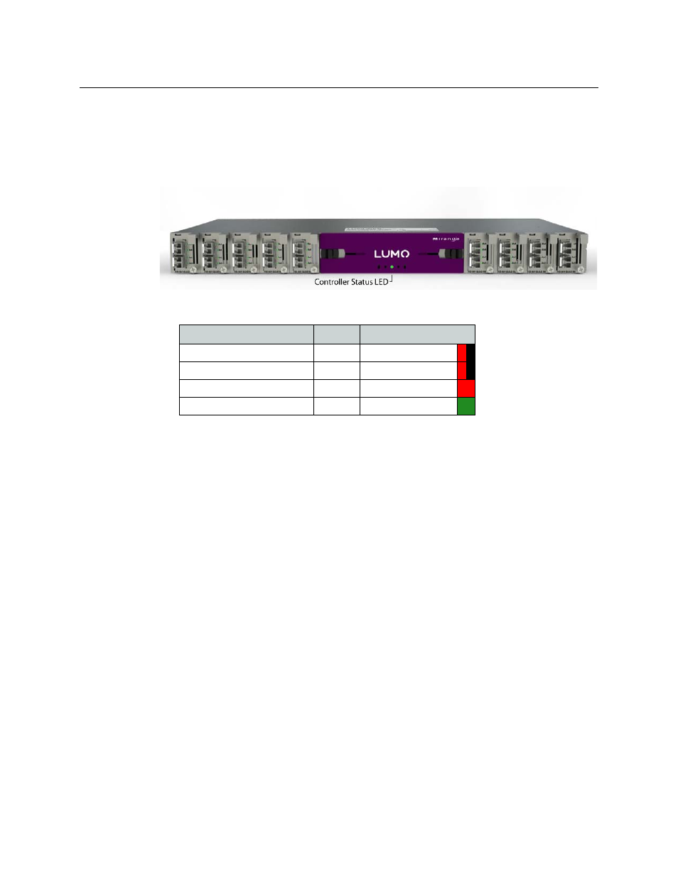
Card-Front Status LED

The status LED is located on the lower-front card-edge of the controller module, and is visible
through the front access door of the LUMO frame. This multi-color LED indicates the status of
the controller card by color, and by flashing/steady illumination.

The table shows how the various error conditions are flagged on the LUMO-CPU-ETH status LED.

The status LED can display only one alarm/status, so it displays only the highest priority. For
example if there is an internal error, it should display RED. But if at the same time the chassis fan
has failed, then the LED will display FLASHING RED.

Be aware that a high priority alarm can mask a lower priority one.

Configuring the LUMO-CPU-ETH Controller

This section introduces the operating features of the LUMO-CPU-ETH controller, and describes
how to access and control them using the iControl interface.

See

Using the iControl interface

on page 22 for instructions on accessing the iControl interface.

The following topics are covered:

Identification

. . . . . . . . . . . . . . . . . . . . . . . . . . . . . . . . . . . . . . . . . . . . . . . . . . . . . . . . . . . . . . . . . . . . . . . page 24

Status Monitoring

. . . . . . . . . . . . . . . . . . . . . . . . . . . . . . . . . . . . . . . . . . . . . . . . . . . . . . . . . . . . . . . . . . page 25

Network Status

. . . . . . . . . . . . . . . . . . . . . . . . . . . . . . . . . . . . . . . . . . . . . . . . . . . . . . . . . . . . . . . . . . . . . page 28

Data Restoration

. . . . . . . . . . . . . . . . . . . . . . . . . . . . . . . . . . . . . . . . . . . . . . . . . . . . . . . . . . . . . . . . . . . page 28

Factory Alignment

. . . . . . . . . . . . . . . . . . . . . . . . . . . . . . . . . . . . . . . . . . . . . . . . . . . . . . . . . . . . . . . . . . page 30

Time Management.

. . . . . . . . . . . . . . . . . . . . . . . . . . . . . . . . . . . . . . . . . . . . . . . . . . . . . . . . . . . . . . . . . page 31

Alarms

. . . . . . . . . . . . . . . . . . . . . . . . . . . . . . . . . . . . . . . . . . . . . . . . . . . . . . . . . . . . . . . . . . . . . . . . . . . . . page 31

Specifications

. . . . . . . . . . . . . . . . . . . . . . . . . . . . . . . . . . . . . . . . . . . . . . . . . . . . . . . . . . . . . . . . . . . . . . page 34

Alarm/Status

Priority LED

Power supply failure

1

FLASHING RED

Fan failure

1

FLASHING RED

Internal error

2

RED

Normal (no errors)

GREEN