Power up, Operation indicator leds – Grass Valley Kameleon HD Multi-Function Modules v.3.2.0 User Manual
Page 16
16
KAM-HD-MULTI—Instruction Manual
Power Up
Power Up
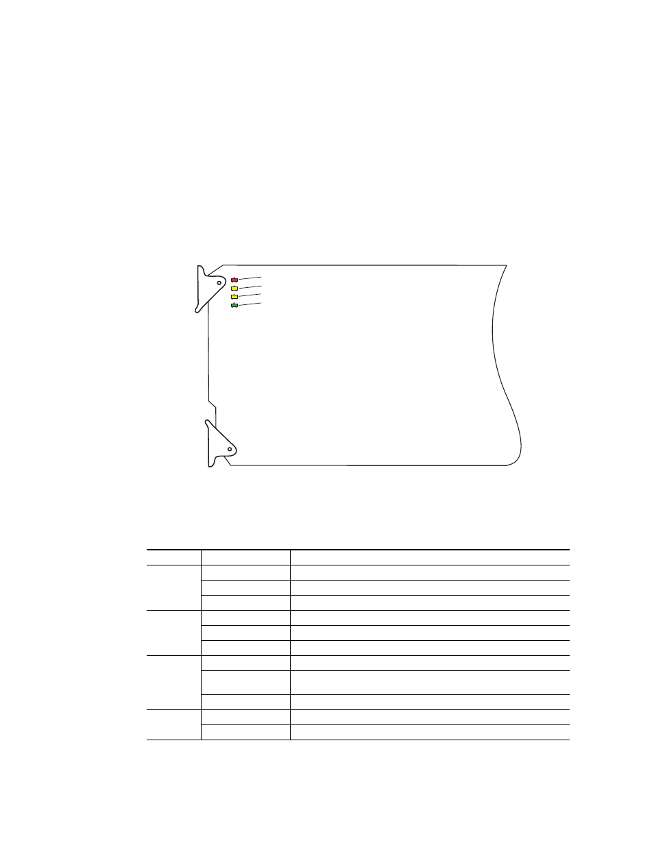
The front LED indicators are illustrated in
. Upon power-up, the
green PWR LED should light and the yellow CONF LED should illuminate
for the duration of module initialization.
Operation Indicator LEDs
With factory default configuration and valid input and reference signals
connected, only the green PWR LED should be on.
Figure 9. Operation Indicator LEDs
A red FAULT LED indicates an error situation and, with the other LEDs,
can indicate the operational conditions presented in
.
Table 1. Indicator LEDs and Conditions Indicated
LED
Indication
Condition
FAULT
(red)
Off
Normal operation.
On continuously
Module has detected an internal fault.
Flashing
Frame reference or video input is missing, input does not match manual selection.
COMM
(yellow)
Off
No activity on frame communication bus.
Long flash
Location Command received by the module from a remote control system.
Short flash
The new system configuration is being stored to the module.
CONF
(yellow)
Off
Module is in normal operating mode.
On continuously
Module is initializing, changing operating modes or updating firmware. Simultaneous
CONF and FAULT LEDs on indicate FPGA load error.
Long flash
Location Command received by the module from a remote control system.
PWR
(green)
Off
No power to module or module’s DC/DC converter failed.
On continuously
Normal operation, module is powered.
8341_03
FAULT LED
COMM LED
CONF LED
POWER LED