Configuration procedure, Verifying the configuration, N in – H3C Technologies H3C S12500 Series Switches User Manual
Page 86: Figure 34
72
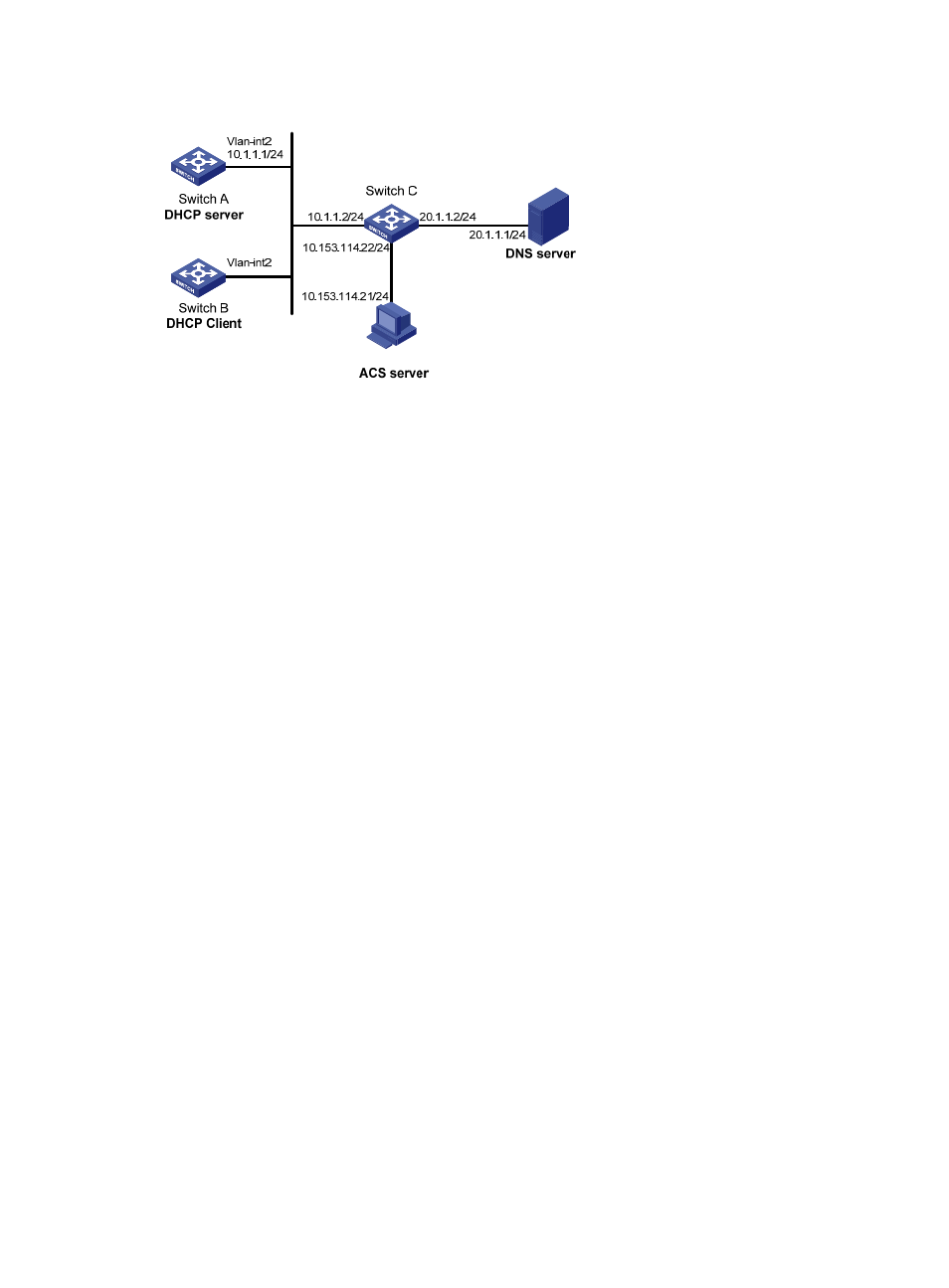
Figure 34 Network diagram
Configuration procedure
1.
Configure Switch A:
# Configure the IP address of VLAN-interface 2.
[SwitchA] interface vlan-interface 2
[SwitchA-Vlan-interface2] ip address 10.1.1.1 24
[SwitchA-Vlan-interface2] quit
# Enable the DHCP service.
[SwitchA] dhcp enable
# Exclude an IP address from automatic allocation.
[SwitchA] dhcp server forbidden-ip 10.1.1.2
# Configure DHCP address pool 0 and specify the subnet, lease duration, DNS server address,
and a static route to subnet 20.1.1.0/24. The ACS address is http://10.153.114.21:9090.
[SwitchA] dhcp server ip-pool 0
[SwitchA-dhcp-pool-0] network 10.1.1.0 mask 255.255.255.0
[SwitchA-dhcp-pool-0] expired day 10
[SwitchA-dhcp-pool-0] dns-list 20.1.1.1
[SwitchA-dhcp-pool-0] option 121 hex 18 14 01 01 0A 01 01 02
[SwitchA-dhcp-pool-0] option 43 hex 01266874 74703A2F 2F31302E 3135332E 3131342E
32313A39 30393020 62596D73 20696D63 62696D73
2.
Configure Switch B:
# Enable the DHCP client on VLAN-interface 2.
[SwitchB] interface vlan-interface 2
[SwitchB-Vlan-interface2] ip address dhcp-alloc
Verifying the configuration
# Use the display dhcp client command to display the IP address and other network parameters assigned
to Switch B.
[SwitchB-Vlan-interface2] display dhcp client verbose