Configuration procedure – H3C Technologies H3C S12500 Series Switches User Manual
Page 243
229
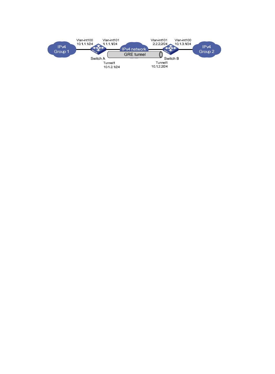
Figure 100 Network diagram
Configuration procedure
Before the configuration, make sure Switch A and Switch B can reach each other.
1.
Configure Switch A:
# Configure an IPv4 address for interface GigabitEthernet 3/0/1.
[SwitchA] vlan 100
[SwitchA-vlan100] port GigabitEthernet 3/0/1
[SwitchA-vlan100] quit
[SwitchA] interface vlan-interface 100
[SwitchA-Vlan-interface100] ip address 10.1.1.1 255.255.255.0
[SwitchA-Vlan-interface100] quit
# Configure an IPv4 address for interface GigabitEthernet 3/0/2, the physical interface of the
tunnel.
[SwitchA] vlan 101
[SwitchA-vlan101] port GigabitEthernet 3/0/2
[SwitchA-vlan101] quit
[SwitchA] interface vlan-interface 101
[SwitchA-Vlan-interface101] ip address 1.1.1.1 255.255.255.0
[SwitchA-Vlan-interface101] quit
# Create a tunnel interface Tunnel1.
[SwitchA] interface tunnel 1
# Configure an IPv4 address for the tunnel interface.
[SwitchA-Tunnel1] ip address 10.1.2.1 255.255.255.0
# Configure the tunnel encapsulation mode as GRE over IPv4.
[SwitchA-Tunnel1] tunnel-protocol gre
# Configure a source address for the tunnel interface (IP address of the VLAN interface to which
GigabitEthernet 3/0/2 belongs).
[SwitchA-Tunnel1] source vlan-interface 101
# Configure a destination address for the tunnel interface (IP address of the VLAN interface to
which GigabitEthernet 3/0/2 of Switch B belongs).
[SwitchA-Tunnel1] destination 2.2.2.2
[SwitchA-Tunnel1] quit
# Configure a static route from Switch A through tunnel interface Tunnel1 to Group 2.
[SwitchA] ip route-static 10.1.3.0 255.255.255.0 tunnel 1
2.
Configure Switch B:
# Configure an IPv4 address for interface GigabitEthernet 3/0/1.
[SwitchB] vlan 100