Configuration example, Network requirements, Configuration procedure – H3C Technologies H3C S12500 Series Switches User Manual
Page 233
219
Step Command
Remarks
7.
Specify the service
card for forwarding
the traffic on the
interface (in
standalone mode).
service slot slot-number
Optional.
Not specified by default.
8.
Return to system view.
quit
N/A
Configuration example
IMPORTANT:
By default, Ethernet, VLAN, and aggregate interfaces are down. To configure such an interface, bring the
interface up by executing the undo shutdown command.
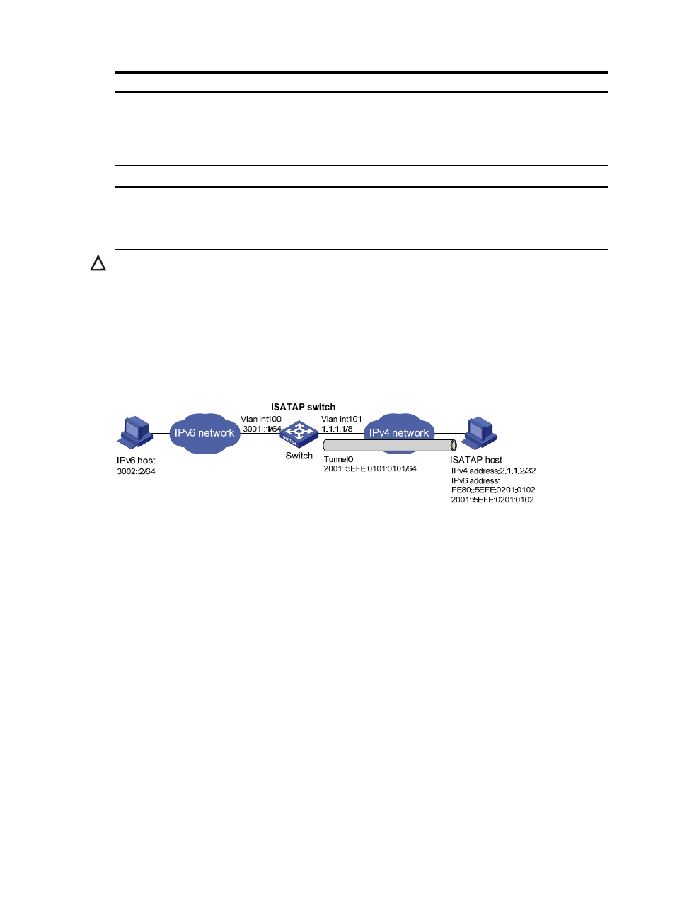
Network requirements
As shown in
, configure an ISATAP tunnel between the switch and the ISATAP host so the ISATAP
host in the IPv4 network can access the IPv6 network.
Figure 92 Network diagram
Configuration procedure
Make sure the corresponding VLAN interfaces have been created on the switch.
Make sure VLAN-interface 101 on the ISATAP switch and the ISATAP host can reach each other.
•
Configure the switch:
# Enable IPv6.
[Switch] ipv6
# Configure addresses for interfaces.
[Switch] interface vlan-interface 100
[Switch-Vlan-interface100] ipv6 address 3001::1/64
[Switch-Vlan-interface100] quit
[Switch] interface vlan-interface 101
[Switch-Vlan-interface101] ip address 1.1.1.1 255.0.0.0
[Switch-Vlan-interface101] quit
# Configure an ISATAP tunnel.
[Switch] interface tunnel 0
[Switch-Tunnel0] ipv6 address 2001::5efe:0101:0101 64
[Switch-Tunnel0] source vlan-interface 101