Troubleshooting gre, Symptom, Solution – H3C Technologies H3C S12500 Series Switches User Manual
Page 246
232
[SwitchB-Vlan-interface101] ip address 1.1.1.2 255.255.255.0
[SwitchB-Vlan-interface101] quit
# Create a tunnel interface Tunnel1.
[SwitchB] interface tunnel 1
# Configure an IPv6 address for the tunnel interface.
[SwitchB-Tunnel1] ipv6 address 2001::2 64
# Configure the tunnel encapsulation mode as GRE over IPv4.
[SwitchB-Tunnel1] tunnel-protocol gre
# Configure a source address for the tunnel interface (IP address of the VLAN interface to which
GigabitEthernet 3/0/2 belongs).
[SwitchB-Tunnel1] source 1.1.1.2
# Configure a destination address for the tunnel interface (IP address of the VLAN interface to
which GigabitEthernet 3/0/2 of Switch A belongs).
[SwitchB-Tunnel1] destination 1.1.1.1
[SwitchB-Tunnel1] quit
# Configure a static route from Switch B through tunnel interface Tunnel1 to Group 1.
[SwitchB] ipv6 route-static 3001:: 64 Tunnel 1
Troubleshooting GRE
The key to configuring GRE is to keep the configurations consistent. This section analyzes one type of fault
for illustration, with the scenario shown in
.
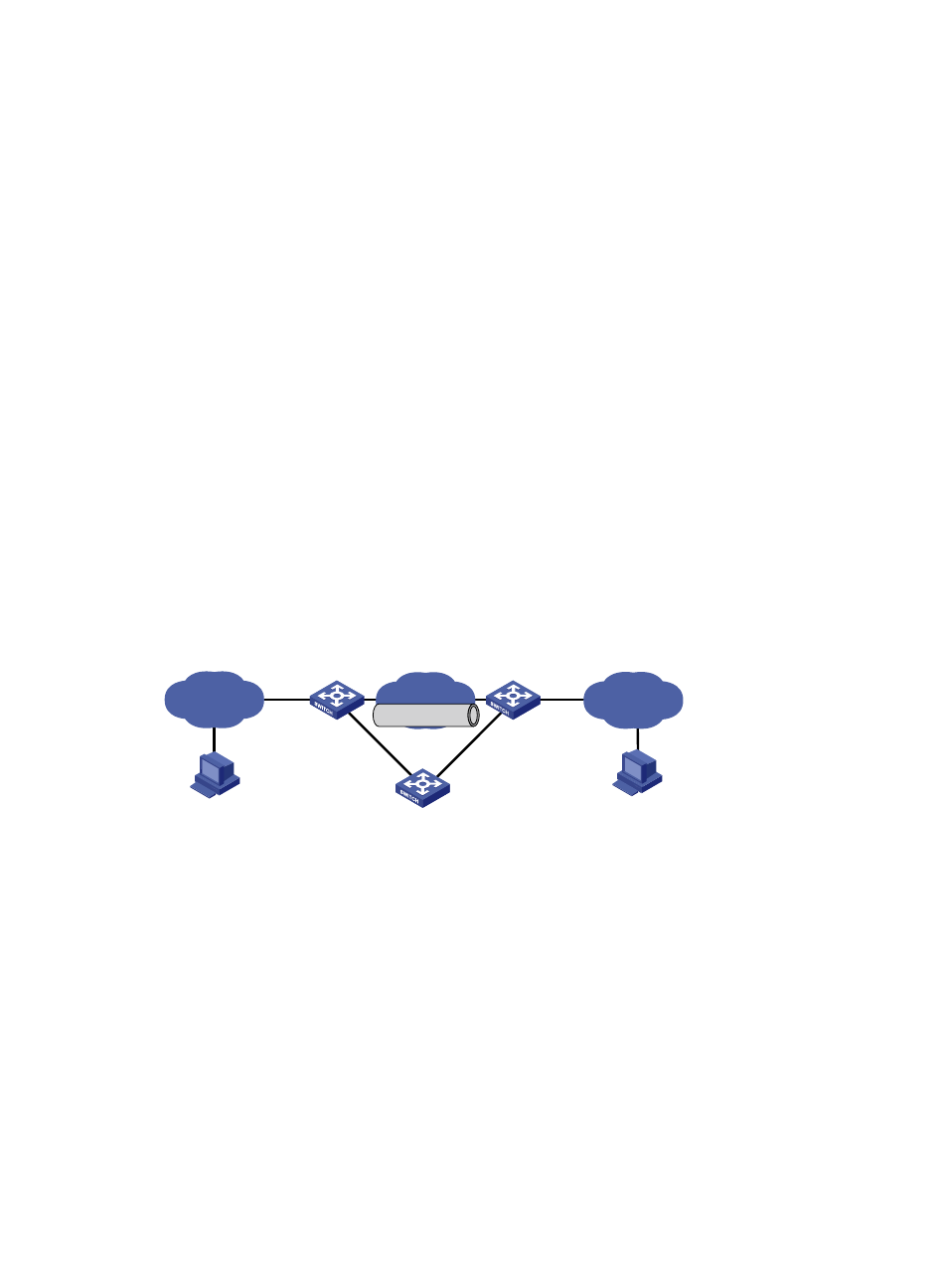
Figure 102 Network diagram
Symptom
The interfaces at both ends of the tunnel are configured correctly and can ping each other, but Host A
and Host B cannot ping each other.
Solution
•
On Switch A and Switch C, execute the display ip routing-table command in any view. On Switch
A, observe whether there is a route from Switch A through Tunnel 0 to 10.2.0.0/16. On Switch C,
observe whether there is a route from Switch C through Tunnel 0 to 10.1.0.0/16.
•
If an expected static route is missing, use the ip route-static command in system view to configure.
For example, configure a static route on Switch A as follows:
[SwitchA] ip route-static 10.2.0.0 255.255.0.0 tunnel 0
IP network
IP network
Switch A
Switch B
Switch C
Host A
Host B
10.1.1.1/16
10.2.1.1/16
Tunnel0
Tunnel0
IP network
GRE Tunnel